Toyota Venza: Components
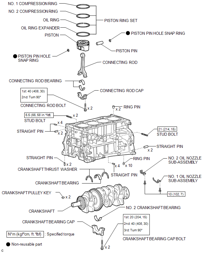
COMPONENTS
ILLUSTRATION
 Precaution
PRECAUTION
HINT:
Any digits beyond the 0.01 mm (1/1000 in.) place for standard, minimum
and maximum values should be used as a reference only.
When both standard and maximum or minim ...
 Disassembly
DISASSEMBLY
PROCEDURE
1. INSPECT CONNECTING ROD THRUST CLEARANCE
(a) Using a dial indicator, measure the thrust clearance while moving
the connecting rod back and forth.
Standard ...
Other materials about Toyota Venza:
How To Proceed With Troubleshooting
HOW TO PROCEED WITH TROUBLESHOOTING
1. OPERATION FLOW
HINT:
Perform troubleshooting in accordance with the procedure below. The following
is an outline of basic troubleshooting procedure. Confirm the troubleshooting procedure
for the circuit you are wor ...
XM Tuner Antenna Disconnected (B15FE,B15FF)
DESCRIPTION
These DTCs are stored when a malfunction occurs in the roof antenna assembly
which is connected to the stereo component tuner assembly.
DTC No.
DTC Detection Condition
Trouble Area
B15FE
...
How To Proceed With Troubleshooting
CAUTION / NOTICE / HINT
HINT:
The back door closer system troubleshooting procedure is based on the
premise that the power back door system is operating normally. Check the
power back door system first before troubleshooting the back door clo ...

0.1426