Toyota Venza: Clearance Sonar Main Switch
Components
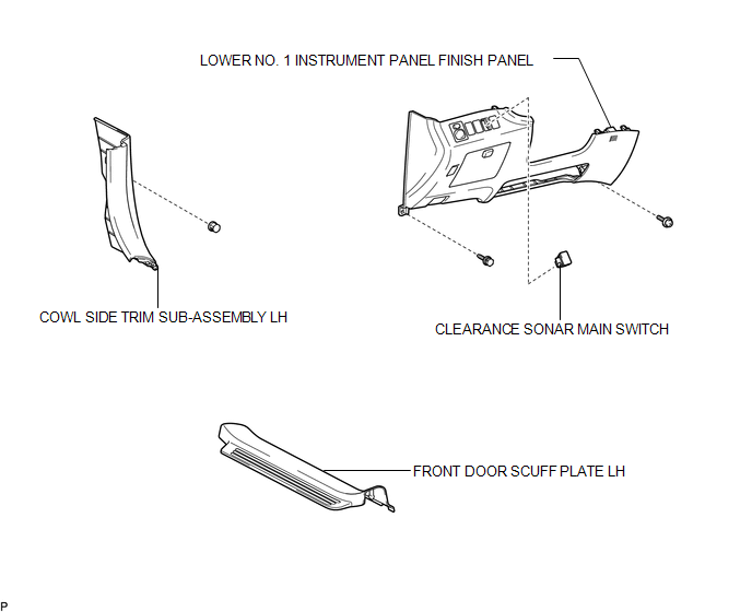
COMPONENTS
ILLUSTRATION
Removal
REMOVAL
PROCEDURE
1. REMOVE FRONT DOOR SCUFF PLATE LH
.gif)
2. REMOVE COWL SIDE TRIM SUB-ASSEMBLY LH
3. REMOVE LOWER NO. 1 INSTRUMENT PANEL FINISH PANEL
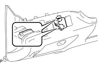
4. REMOVE CLEARANCE SONAR MAIN SWITCH
|
(a) Disengage the 2 claws and remove the clearance sonar main switch. |
|
Inspection
INSPECTION
PROCEDURE
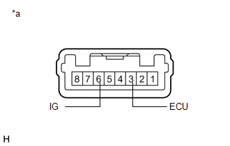
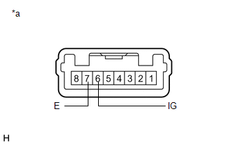
1. INSPECT BACK SONAR OR CLEARANCE SONAR SWITCH ASSEMBLY
|
(a) Measure the resistance according to the value(s) in the table below. Standard Resistance:
If the result is not as specified, replace the back sonar or clearance sonar switch assembly. |
|
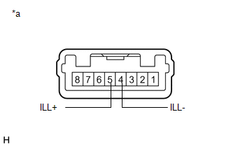
(b) Check that the switch illuminates.
|
(1) Apply battery voltage to the back sonar or clearance sonar switch assembly and check that the switch illuminates. OK:
If the result is not as specified, replace the back sonar or clearance sonar switch assembly. |
|
(c) Check switch indicator operation.
|
(1) Apply battery voltage to the back sonar or clearance sonar switch assembly and check that the switch indicator illuminates. OK:
If the result is not as specified, replace the back sonar or clearance sonar switch assembly. |
|
Installation
INSTALLATION
PROCEDURE
1. INSTALL CLEARANCE SONAR MAIN SWITCH
(a) Engage the 2 claws to install the clearance sonar main switch.
2. INSTALL LOWER NO. 1 INSTRUMENT PANEL FINISH PANEL
.gif)
3. INSTALL COWL SIDE TRIM SUB-ASSEMBLY LH
4. INSTALL FRONT DOOR SCUFF PLATE LH

 Clearance Warning Buzzer
Components
COMPONENTS
ILLUSTRATION
Removal
REMOVAL
PROCEDURE
1. REMOVE FRONT DOOR SCUFF PLATE LH
2. REMOVE COWL SIDE TRIM SUB-ASSEMBLY LH
3. REMOVE LOWER NO. 1 INSTRUMENT PANEL FIN ...
Other materials about Toyota Venza:
Inspection
INSPECTION
PROCEDURE
1. INSPECT THROTTLE BODY ASSEMBLY
Text in Illustration
*1
Component without harness connected
(Throttle Body)
(a) Check that the throttle valve opens and closes smoothly.
(b) Check that there is no ...
Diagnostic Trouble Code Chart
DIAGNOSTIC TROUBLE CODE CHART
HINT:
If a trouble code is stored during the DTC check, inspect the trouble areas listed
for that code. For details of the code, refer to the "See page" below.
1. CERTIFICATION ECU (SMART KEY ECU ASSEMBLY) DIAGNOSTI ...
Inspection
INSPECTION
PROCEDURE
1. INSPECT PRELOAD
(a) Secure the steering column assembly in a vise.
Text in Illustration
*1
Service Nut
*2
Steering Wheel Assembly Set Nut
...

0.1337