Toyota Venza: Child Restraint Seat Tether Anchor
Components
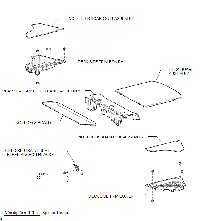
COMPONENTS
ILLUSTRATION
Installation
INSTALLATION
PROCEDURE
1. INSTALL CHILD RESTRAINT SEAT TETHER ANCHOR BRACKET
|
(a) Engage the guide. |
|
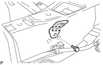
(b) Install the child restraint seat tether anchor bracket with the bolt.
Torque:
31 N·m {316 kgf·cm, 23 ft·lbf}
HINT:
Use the same procedure for the other 2 child restraint seat tether anchor brackets.
2. INSTALL REAR SEAT SUB FLOOR PANEL ASSEMBLY
.gif)
3. INSTALL NO. 1 DECK BOARD
4. INSTALL DECK SIDE TRIM BOX RH
5. INSTALL NO. 2 DECK BOARD SUB-ASSEMBLY
6. INSTALL DECK SIDE TRIM BOX LH
7. INSTALL NO. 3 DECK BOARD SUB-ASSEMBLY
8. INSTALL DECK BOARD ASSEMBLY
Removal
REMOVAL
PROCEDURE
1. REMOVE DECK BOARD ASSEMBLY
.gif)
2. REMOVE NO. 3 DECK BOARD SUB-ASSEMBLY
3. REMOVE DECK SIDE TRIM BOX LH
4. REMOVE NO. 2 DECK BOARD SUB-ASSEMBLY
5. REMOVE DECK SIDE TRIM BOX RH
6. REMOVE NO. 1 DECK BOARD
7. REMOVE REAR SEAT SUB FLOOR PANEL ASSEMBLY
8. REMOVE CHILD RESTRAINT SEAT TETHER ANCHOR BRACKET
|
(a) Remove the bolt. |
|
.png)
(b) Disengage the guide and remove the child restraint seat tether anchor bracket.
HINT:
Use the same procedure for the other 2 child restraint seat tether anchor brackets.
 Seat Belt
...
 Front Passenger Seat Belt Warning Light
Components
COMPONENTS
ILLUSTRATION
Installation
INSTALLATION
PROCEDURE
1. INSTALL ACCESSORY METER ASSEMBLY (w/o Rear View Monitor System)
(a) Connect the connector.
(b) Engage the 2 clam ...
Other materials about Toyota Venza:
System Diagram
SYSTEM DIAGRAM
Communication Table
Transmitting ECU (Transmitter)
Receiving ECU
Signal
Communication Method
Main body ECU (Driver side junction block assembly)
Certification ECU (Sm ...
Short in Driver Side Squib Circuit (B1800/51-B1803/51)
DESCRIPTION
The driver side squib circuit consists of the center airbag sensor assembly,
spiral cable and steering pad.
The center airbag sensor assembly uses this circuit to deploy the airbag when
deployment conditions are met.
These DTCs are stored wh ...
Charge Warning Light Comes ON while Driving
PROCEDURE
1.
CHECK LOCK FUNCTION OF GENERATOR CLUTCH PULLEY
(a) Check the lock function with the pulley installed in the vehicle.
(1) Visually check that the rotor in the generator operates with the engine running.
(b) Check ...

0.157