Toyota Venza: 4wd Control Ecu
Components
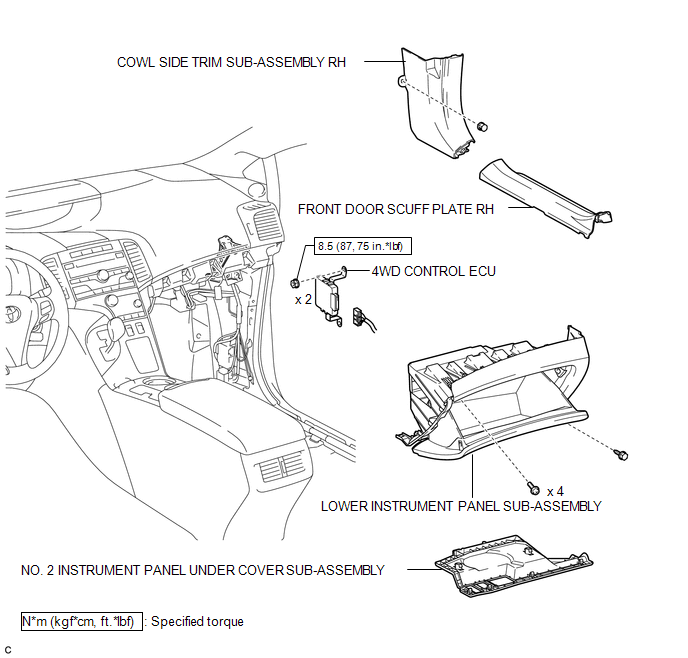
COMPONENTS
ILLUSTRATION
Removal
REMOVAL
PROCEDURE
1. REMOVE FRONT DOOR SCUFF PLATE RH
2. REMOVE COWL SIDE TRIM SUB-ASSEMBLY RH
3. REMOVE NO. 2 INSTRUMENT PANEL UNDER COVER SUB-ASSEMBLY
4. REMOVE LOWER INSTRUMENT PANEL SUB-ASSEMBLY
.gif)
5. REMOVE 4WD CONTROL ECU
|
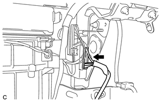
(a) Disconnect the connector. |
|
|
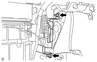
(b) Remove the 2 nuts and ECU. |
|
Installation
INSTALLATION
PROCEDURE
1. INSTALL 4WD CONTROL ECU
|
(a) Install the ECU with the 2 nuts. Torque: 8.5 N·m {87 kgf·cm, 75 in·lbf} |
|
.png)
|
(b) Connect the connector. |
|
.png)
2. INSTALL LOWER INSTRUMENT PANEL SUB-ASSEMBLY
.gif)
3. INSTALL NO. 2 INSTRUMENT PANEL UNDER COVER SUB-ASSEMBLY
4. INSTALL COWL SIDE TRIM SUB-ASSEMBLY RH
5. INSTALL FRONT DOOR SCUFF PLATE RH


Other materials about Toyota Venza:
Data List / Active Test
DATA LIST / ACTIVE TEST
1. DATA LIST
HINT:
Using the Techstream to read the Data List allows the values or states of switches,
sensors, actuator and other items to be read without removing any parts. This non-intrusive
inspection can be very useful beca ...
Identification Information
Vehicle Identification And Serial Numbers
VEHICLE IDENTIFICATION AND SERIAL NUMBERS
1. VEHICLE IDENTIFICATION NUMBER
(a) The vehicle identification number is stamped on the vehicle body and on the
certification label as shown in the illustration.
A: ...
Vehicle Speed Signal Malfunction (B2282)
DESCRIPTION
The power management control ECU receives vehicle speed information using 2 methods.
It receives a speed signal from the meter ECU. It also receives speed information
from the meter ECU via CAN. If the information sent using these 2 methods is ...

0.1149