Toyota Venza: Windshield Deicer does not Operate
DESCRIPTION
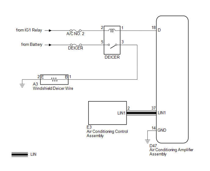
When the rear window defogger switch on the air conditioning control assembly is pressed, the operation signal is transmitted to the air conditioning amplifier assembly through the LIN communication line. When the air conditioning amplifier assembly receives the signal, it turns on the DEICER relay to operate the windshield deicer.
WIRING DIAGRAM
CAUTION / NOTICE / HINT
NOTICE:
Inspect the fuses for circuits related to this system before performing the following inspection procedure.
PROCEDURE
|
1. |
CHECK WINDOW DEFOGGER SYSTEM |
(a) Turn the ignition switch to ON, press the rear window defogger switch, and
check that the window defogger operates (See page
.gif) ).
).
OK:
The window defogger system operates normally.
| NG | .gif) |
GO TO WINDOW DEFOGGER SYSTEM |
|
.gif)
|
2. |
INSPECT DEICER RELAY |
|
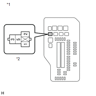
(a) Remove the DEICER relay from the engine room relay block. |
|
.png)
(b) Measure the resistance according to the value(s) in the table below.
Standard Resistance:
|
Tester Connection |
Condition |
Specified Condition |
|---|---|---|
|
3 - 5 |
Battery voltage applied between terminals 1 and 2 |
Below 1 Ω |
|
3 - 5 |
Battery voltage not applied between terminals 1 and 2 |
10 kΩ or higher |
| NG | |
REPLACE DEICER RELAY |
|
|
3. |
CHECK HARNESS AND CONNECTOR (DEICER RELAY POWER SOURCE) |
|
(a) Measure the voltage according to the value(s) in the table below. Standard Voltage:
|
|
| NG | |
REPAIR OR REPLACE HARNESS OR CONNECTOR |
|
|
4. |
CHECK HARNESS AND CONNECTOR (DEICER RELAY - AIR CONDITIONING AMPLIFIER ASSEMBLY) |
|
(a) Disconnect the D47 air conditioning amplifier assembly connector. |
|
(b) Measure the resistance according to the value(s) in the table below.
Standard Resistance:
|
Tester Connection |
Condition |
Specified Condition |
|---|---|---|
|
Engine room relay block DEICER relay terminal 1 - D47-18 (D) |
Always |
Below 1 Ω |
|
D47-14 (GND) - Body ground |
Always |
Below 1 Ω |
|
D47-18 (D) - Body ground |
Always |
10 kΩ or higher |
|
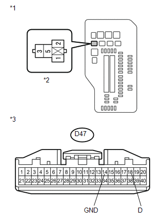
*1 |
Engine Room Relay Block |
|
*2 |
DEICER Relay Terminal |
|
*3 |
Front view of wire harness connector (to Air Conditioning Amplifier Assembly) |
| NG | |
REPAIR OR REPLACE HARNESS OR CONNECTOR |
|
|
5. |
CHECK HARNESS AND CONNECTOR (DEICER RELAY POWER SOURCE) |
|
(a) Measure the voltage according to the value(s) in the table below. Standard Voltage:
|
|
| NG | |
REPAIR OR REPLACE HARNESS OR CONNECTOR |
|
|
6. |
CHECK HARNESS AND CONNECTOR (DEICER RELAY - WINDSHIELD DEICER WIRE) |
|
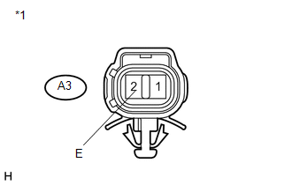
(a) Disconnect the A3 windshield deicer wire connector. |
|

(b) Measure the resistance according to the value(s) in the table below.
Standard Resistance:
|
Tester Connection |
Condition |
Specified Condition |
|---|---|---|
|
A3-1 (B) - engine room relay block DEICER relay terminal 3 |
Always |
Below 1 Ω |
|
A3-1 (B) - Body ground |
Always |
10 kΩ or higher |
|
Engine room relay block DEICER relay terminal 3 - Body ground |
Always |
10 kΩ or higher |
|
*1 |
Engine Room Relay Block |
|
*2 |
DEICER Relay Terminal |
|
*3 |
Front view of wire harness connector (to Windshield Deicer Wire) |
| NG | |
REPAIR OR REPLACE HARNESS OR CONNECTOR |
|
|
7. |
CHECK HARNESS AND CONNECTOR (WINDSHIELD DEICER WIRE - BODY GROUND) |
|
(a) Measure the resistance according to the value(s) in the table below. Standard Resistance:
|
|
| OK | |
REPLACE WINDSHIELD GLASS (WINDSHIELD DEICER WIRE) |
| NG | |
REPAIR OR REPLACE HARNESS OR CONNECTOR |
 Terminals Of Ecu
TERMINALS OF ECU
1. CHECK AIR CONDITIONING AMPLIFIER ASSEMBLY
(a) Disconnect the D47 air conditioning amplifier assembly connector.
(b) Measure the voltage and resistance according to the value(s ...
 Windshield Glass
...
Other materials about Toyota Venza:
Camshaft Position "A" - Timing Over-Advanced or System Performance (Bank 1)
(P0011,P0012)
DESCRIPTION
Refer to DTC P0010 (See page ).
DTC No.
DTC Detection Condition
Trouble Area
P0011
The valve timing is stuck at a certain value when in the advance range
(1 trip detection logic).
...
Removal
REMOVAL
PROCEDURE
1. REMOVE NO. 1 ENGINE UNDER COVER
2. REMOVE NO. 2 ENGINE UNDER COVER
3. REMOVE WINDSHIELD WIPER MOTOR AND LINK
(a) Remove the windshield wiper motor and link (See page
).
4. REMOVE OUTER COWL TOP PANEL SUB-ASSEMBLY
5. DRAIN ENGIN ...
Installation
INSTALLATION
CAUTION / NOTICE / HINT
HINT:
Use the same procedure for the RH side and LH side.
The procedure listed below is for the LH side.
PROCEDURE
1. INSTALL DOOR SIDE AIRBAG SENSOR
(a) Check that the ignition switch is off.
(b) C ...

0.1367