Toyota Venza: VC Output Circuit
DESCRIPTION
The ECM constantly generates 5 V of power from battery voltage supplied to the +B (BATT) terminal to operate the microprocessor. The ECM also provides this power to the sensors through the VC output circuit.
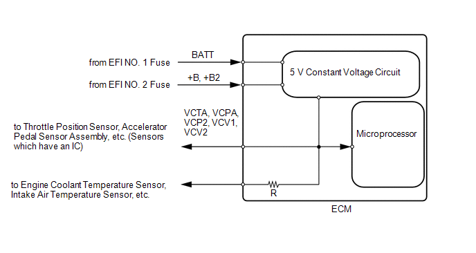
When the VC circuit is short-circuited, the microprocessor in the ECM and sensors that are supplied with power through the VC circuit are inactivated because the power is not supplied from the VC circuit. Under this condition, the system does not start up and the MIL does not illuminate even if the system malfunctions.
HINT:
Under normal conditions, the MIL is illuminated when the ignition switch is turned to ON. The MIL turns off when the engine is started.
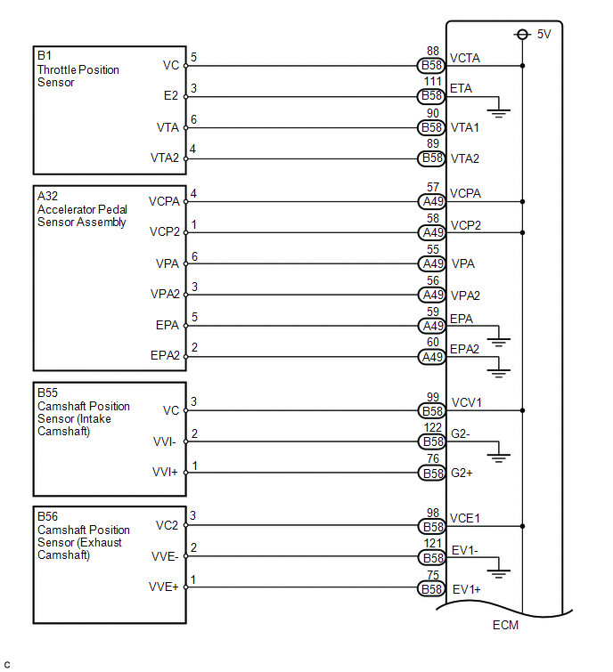
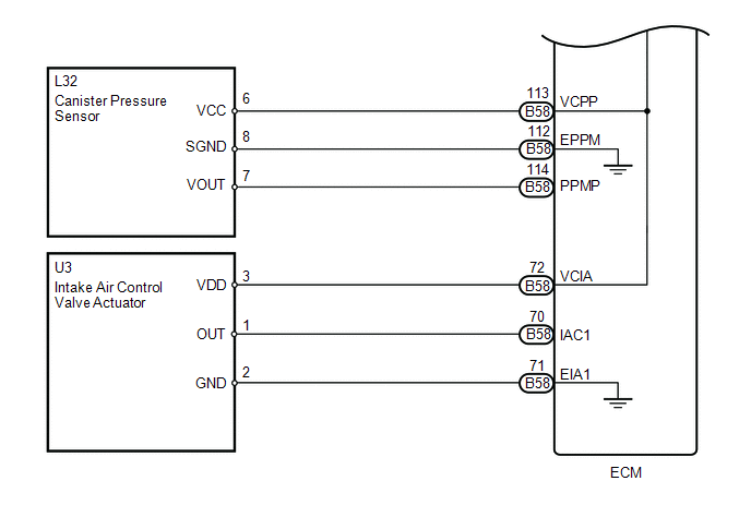
WIRING DIAGRAM
PROCEDURE
|
1. |
CHECK MIL |
(a) Check that the Malfunction Indicator Lamp (MIL) turns on when turning the ignition switch to ON.
OK:
MIL turns on.
| OK | .gif) |
PROCEED TO NEXT SUSPECTED AREA SHOWN IN PROBLEM SYMPTOMS TABLE |
|
.gif)
|
2. |
CHECK COMMUNICATION BETWEEN TECHSTREAM AND ECM |
(a) Connect the Techstream to the DLC3.
(b) Turn the ignition switch to ON.
(c) Turn the Techstream on.
(d) Check the communication between the Techstream and ECM.
|
Result |
Proceed to |
|---|---|
|
Communication is not possible |
A |
|
Communication is possible |
B |
| B | |
GO TO MIL CIRCUIT |
|
|
3. |
CHECK MIL (THROTTLE POSITION SENSOR) |
(a) Disconnect the throttle body connector.
(b) Turn the ignition switch to ON.
(c) Check the MIL.
|
Result |
Proceed to |
|---|---|
|
MIL does not illuminate |
A |
|
MIL illuminates |
B |
HINT:
Perform "Inspection After Repair" after replacing the throttle body (See page
.gif) ).
).
| B | |
REPLACE THROTTLE BODY |
|
|
4. |
CHECK MIL (ACCELERATOR PEDAL SENSOR ASSEMBLY) |
(a) Disconnect the accelerator pedal sensor assembly connector.
(b) Turn the ignition switch to ON.
(c) Check the MIL.
|
Result |
Proceed to |
|---|---|
|
MIL does not illuminate |
A |
|
MIL illuminates |
B |
| B | |
REPLACE ACCELERATOR PEDAL SENSOR ASSEMBLY |
|
|
5. |
CHECK MIL (CANISTER PUMP MODULE) |
(a) Disconnect the canister pump module connector.
(b) Turn the ignition switch to ON.
(c) Check the MIL.
|
Result |
Proceed to |
|---|---|
|
MIL does not illuminate |
A |
|
MIL illuminates |
B |
| B | |
REPLACE CHARCOAL CANISTER ASSEMBLY |
|
|
6. |
CHECK MIL (CAMSHAFT POSITION SENSOR (FOR INTAKE CAMSHAFT)) |
(a) Disconnect the camshaft position sensor (for intake camshaft) connector.
(b) Turn the ignition switch to ON.
(c) Check the MIL.
|
Result |
Proceed to |
|---|---|
|
MIL does not illuminate |
A |
|
MIL illuminates |
B |
| B | |
REPLACE CAMSHAFT POSITION SENSOR |
|
|
7. |
CHECK MIL (CAMSHAFT POSITION SENSOR (FOR EXHAUST CAMSHAFT)) |
(a) Disconnect the camshaft position sensor (for exhaust camshaft) connector.
(b) Turn the ignition switch to ON.
(c) Check the MIL.
|
Result |
Proceed to |
|---|---|
|
MIL does not illuminate |
A |
|
MIL illuminates |
B |
| B | |
REPLACE CAMSHAFT POSITION SENSOR |
|
|
8. |
CHECK MIL (INTAKE AIR CONTROL VALVE ACTUATOR) |
(a) Disconnect the intake air control valve actuator connector.
(b) Turn the ignition switch to ON.
(c) Check the MIL.
|
Result |
Proceed to |
|---|---|
|
MIL does not illuminate |
A |
|
MIL illuminates |
B |
| B | |
REPLACE INTAKE AIR CONTROL VALVE ACTUATOR |
|
|
9. |
CHECK HARNESS AND CONNECTOR (VC CIRCUIT) |
(a) Disconnect the throttle body connector.
(b) Disconnect the accelerator pedal sensor assembly connector.
(c) Disconnect the canister pump module connector.
(d) Disconnect the camshaft position sensor (for intake camshaft) connector.
(e) Disconnect the camshaft position sensor (for exhaust camshaft) connector.
(f) Disconnect the intake air control valve actuator connector.
(g) Disconnect the ECM connectors.
(h) Measure the resistance according to the value(s) in the table below.
Standard Resistance (Check for Short):
|
Tester Connection |
Condition |
Specified Condition |
|---|---|---|
|
A49-57 (VCPA) - Body ground |
Always |
10 kΩ or higher |
|
A49-58 (VCP2) - Body ground |
Always |
10 kΩ or higher |
|
B58-72 (VCIA) - Body ground |
Always |
10 kΩ or higher |
|
B58-88 (VCTA) - Body ground |
Always |
10 kΩ or higher |
|
B58-98 (VCE1) - Body ground |
Always |
10 kΩ or higher |
|
B58-99 (VCV1) - Body ground |
Always |
10 kΩ or higher |
|
B58-113 (VCPP) - Body ground |
Always |
10 kΩ or higher |
| OK | |
REPLACE ECM |
| NG | |
REPAIR OR REPLACE HARNESS OR CONNECTOR |
 ECM Power Source Circuit
DESCRIPTION
When the ignition switch is turned to ON, the battery voltage is applied to IGSW
of the ECM. The output signal from the MREL terminal of the ECM causes a current
to flow to the coil, ...
 Fuel Pump Control Circuit
DESCRIPTION
1. w/o Smart Key System
When the engine is cranked, the starter relay drive signal output from the ignition
switch is input into the STA terminal of the ECM, and the NE signal generate ...
Other materials about Toyota Venza:
System Diagram
SYSTEM DIAGRAM
Communication Table
Sender
Receiver
Signal
Line
Main body ECU (Driver side junction block assembly)
Sliding roof ECU (Sliding roof drive gear sub-assembly)
Key ...
PBD Pulse Sensor Malfunction (B2222)
DESCRIPTION
A pulse sensor is built into the power back door ECU (power back door
motor unit) to detect foreign objects and the back door position. The pulse
sensor monitors the operating speed of the back door to detect foreign objects.
Th ...
Motor Circuit Malfunction (C1521,C1531-C1534,C1554)
DESCRIPTION
If the power steering ECU detects these DTCs, it will shut off the motor relay
circuit (built into the power steering ECU) and stop power assist. However, power
assist continues if DTC C1533 or C1534 is stored.
DTC No.
D ...

0.1654