Toyota Venza: Ultrasonic Sensor(for Front Side)
Components
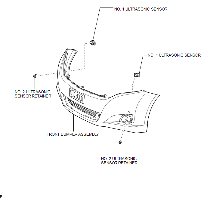
COMPONENTS
ILLUSTRATION
Removal
REMOVAL
PROCEDURE
1. REMOVE FRONT BUMPER ASSEMBLY
(See page .gif) )
)
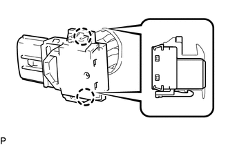
2. REMOVE NO. 1 ULTRASONIC SENSOR
|
(a) Disengage the 2 claws to remove the No. 1 ultrasonic sensor. HINT: Use the same procedure for the RH side and LH side. |
|
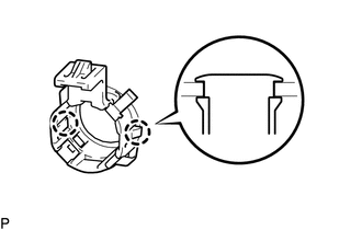
3. REMOVE NO. 2 ULTRASONIC SENSOR RETAINER
|
(a) Disengage the 2 claws to remove the No. 2 ultrasonic sensor retainer from the front bumper assembly. HINT: Use the same procedure for the RH side and LH side. |
|
Inspection
INSPECTION
PROCEDURE
1. INSPECT NO. 1 ULTRASONIC SENSOR
|
(a) Measure the resistance according to the value(s) in the table below. Standard Resistance:
If the result is not as specified, replace the No. 1 ultrasonic sensor. |
|
.png)
Installation
INSTALLATION
PROCEDURE
1. INSTALL NO. 2 ULTRASONIC SENSOR RETAINER
|
(a) Engage the 2 claws to install the No. 2 ultrasonic sensor retainer to the front bumper assembly. Text in Illustration
NOTICE:
HINT:
|
|
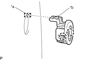
2. INSTALL NO. 1 ULTRASONIC SENSOR
(a) Engage the 2 claws to install the No. 1 ultrasonic sensor to the No. 2 ultrasonic sensor retainer.
NOTICE:
Push the No. 2 ultrasonic sensor retainer from the outside of the front bumper assembly when there is a gap between the No. 2 ultrasonic sensor retainer and the front bumper assembly surface. In this case, do not push on the No. 1ultrasonic sensor.
HINT:
Use the same procedure for the RH side and LH side.
3. INSTALL FRONT BUMPER ASSEMBLY
(See page .gif) )
)
 Television Camera
Components
COMPONENTS
ILLUSTRATION
ILLUSTRATION
Removal
REMOVAL
PROCEDURE
1. REMOVE BACK DOOR PANEL TRIM ASSEMBLY
2. REMOVE REAR WIPER ARM HEAD CAP
3. REMOVE REAR WIPER ARM AND ...

Other materials about Toyota Venza:
Problem Symptoms Table
PROBLEM SYMPTOMS TABLE
HINT:
Use the table below to help determine the cause of the problem symptoms. If multiple
suspected areas are listed, the potential causes of the symptoms are listed in order
of probability in the "Suspected Area" column ...
Terminals Of Ecu
TERMINALS OF ECU
1. CHECK POWER BACK DOOR ECU (POWER BACK DOOR MOTOR UNIT) (w/ POWER BACK DOOR
SYSTEM)
(a) Disconnect the L20 power back door ECU connector.
(b) Measure the voltage and resistance according to the value(s) in the table
below.
...
Fail-safe Chart
FAIL-SAFE CHART
1. FAIL-SAFE FUNCTION
If the following malfunctions occur, the AWD control ECU will stop the
function of 4WD control system or partly change the function to control
the system.
If a malfunction occurs in the senso ...

0.1465