Toyota Venza: Torque Converter Clutch Pressure Control Solenoid Control Circuit Electrical (Shift Solenoid Valve SLU) (P2759)
DESCRIPTION
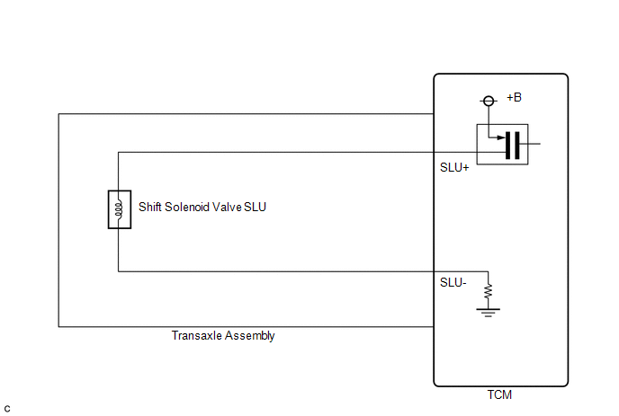
The amount of current flow to the solenoid is controlled by the duty ratio of the TCM output signal. The higher the duty ratio becomes, the higher the lock-up hydraulic pressure becomes during the lock-up operation.
|
DTC No. |
DTC Detection Condition |
Trouble Area |
|---|---|---|
|
P2759 |
Open or short is detected in shift solenoid valve SLU circuit for 1 second or more while driving (1-trip detection logic). |
|
MONITOR DESCRIPTION
When an open or short in a shift solenoid valve (SLU) circuit is detected, the TCM determines there is a malfunction. The TCM will turn on the MIL and store this DTC.
MONITOR STRATEGY
|
Related DTCs |
P2759: Shift solenoid valve SLU/Range check |
|
Required sensors/Components |
Shift solenoid valve SLU |
|
Frequency of operation |
Continuous |
|
Duration |
1 sec. |
|
MIL operation |
Immediate |
|
Sequence of operation |
None |
TYPICAL ENABLING CONDITIONS
All|
The monitor will run whenever the following DTCs are not present |
None |
|
Ignition switch |
ON |
|
Starter |
OFF |
|
Battery voltage |
12 V or more |
|
Battery voltage |
10 V or more and less than 12 V |
|
Target current |
Less than 0.75 A |
|
Battery voltage |
8 V or more |
|
Target current |
0.25 A or more |
TYPICAL MALFUNCTION THRESHOLDS
Condition (A) and (B)|
Output duty cycle |
100% or more |
|
Output duty cycle |
0% or less |
COMPONENT OPERATING RANGE
|
Output duty cycle |
More than 3% and less than 100% |
WIRING DIAGRAM
CAUTION / NOTICE / HINT
NOTICE:
Perform the universal trip to clear permanent DTCs (See page
.gif) ).
).
PROCEDURE
|
1. |
INSPECT TRANSMISSION WIRE (SLU) |
|
(a) Remove the TCM from the transaxle. |
|
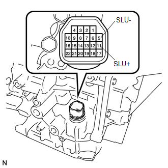
(b) Measure the resistance according to the value(s) in the table below.
Standard Resistance:
|
Tester Connection |
Condition |
Specified Condition |
|---|---|---|
|
11 (SLU+) - 5 (SLU-) |
20°C (68°F) |
5.0 to 5.6 Ω |
|
11 (SLU+) - Body ground or other terminals |
Always |
10 kΩ or higher |
|
5 (SLU-) - Body ground or other terminals |
Always |
10 kΩ or higher |
|
11 (SLU+) - All other terminals except 5 (SLU-) |
Always |
10 kΩ or higher |
|
5 (SLU-) - All other terminals except 11 (SLU+) |
Always |
10 kΩ or higher |
| OK | .gif) |
REPLACE TCM |
|
.gif)
|
2. |
INSPECT SHIFT SOLENOID VALVE SLU |
|
(a) Remove shift solenoid valve SLU. |
|
.png)
(b) Measure the resistance according to the value(s) in the table below.
Standard Resistance:
|
Tester Connection |
Condition |
Specified Condition |
|---|---|---|
|
1 - 2 |
20°C (68°F) |
5.0 to 5.6 Ω |
|
*1 |
Shift Solenoid Valve SLU |
(c) Connect a battery positive (+) lead with a 21 W bulb to terminal 2 and a negative (-) lead to terminal 1 of the solenoid valve connector. Then check that the valve moves and makes an operating sound.
OK:
Valve moves and makes an operating sound.
| OK | |
REPLACE TRANSMISSION WIRE |
| NG | |
REPLACE SHIFT SOLENOID VALVE SLU |
 Lost Communication with ECM / PCM "A" (U0100)
DESCRIPTION
The engine control unit communicates with the TCM using the Controller Area Network
(CAN).
If there is a problem in this communication, the TCM sets a DTC.
DTC No.
...
 Pressure Control Solenoid "D" Electrical (Shift Solenoid Valve SLT) (P2716)
DESCRIPTION
Refer to DTC P2714 (See page ).
DTC No.
DTC Detection Condition
Trouble Area
P2716
Open or short is detected in shift soleno ...
Other materials about Toyota Venza:
Short in Side Squib RH Circuit (B1820/55-B1823/55)
DESCRIPTION
The side squib RH circuit consists of the center airbag sensor assembly and front
seat side airbag assembly RH.
The center airbag sensor assembly uses this circuit to deploy the airbag when
deployment conditions are met.
These DTCs are store ...
Display does not Dim when Light Control Switch is Turned ON
PROCEDURE
1.
CHECK IMAGE QUALITY SETTING
(a) Turn the light control switch to the tail or head position.
(b) Check that the daytime screen setting on the display adjustment screen is
set to on.
Result
...
Horn Circuit
DESCRIPTION
When the theft deterrent system is switched from the armed state to the alarm
sounding state, the main body ECU (driver side junction block assembly) transmits
a signal to cause the horn to sound at intervals of 0.4 seconds.
WIRING DIAGRAM
...

0.1407