Toyota Venza: Tire Pressure Warning Receiver
Components
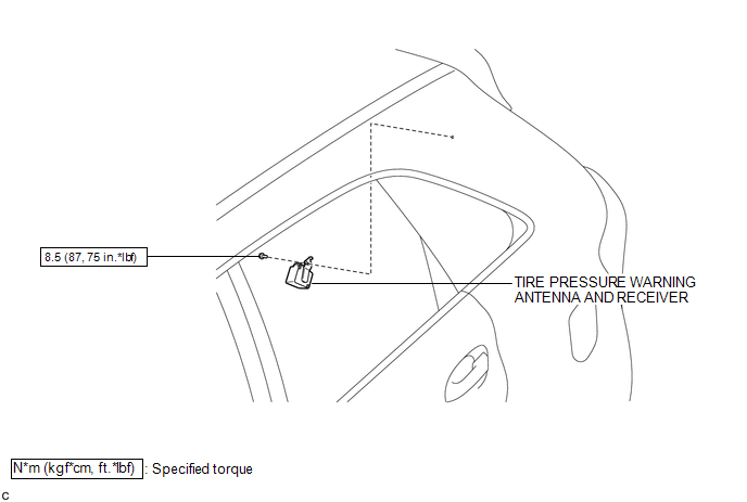
COMPONENTS
ILLUSTRATION
Removal
REMOVAL
PROCEDURE
1. DISCONNECT CABLE FROM NEGATIVE BATTERY TERMINAL
NOTICE:
When disconnecting the cable, some systems need to be initialized after the cable
is reconnected (See page .gif) ).
).
2. REMOVE ROOF SIDE INNER GARNISH ASSEMBLY LH
HINT:
- Refer to the procedures up to "Remove roof side inner garnish assembly"
(See page ).
- Removal should be performed only for the left side.
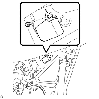
3. REMOVE TIRE PRESSURE WARNING ANTENNA AND RECEIVER
|
(a) Remove the bolt. |
|
|
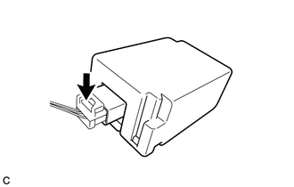
(b) Disconnect the connector to remove the tire pressure warning antenna and receiver. |
|
Installation
INSTALLATION
PROCEDURE
1. INSTALL TIRE PRESSURE WARNING ANTENNA AND RECEIVER
|
(a) Connect the connector. |
|
.png)
|
(b) Engage the 2 tabs into the holes as shown in the illustration to install the tire pressure warning antenna and receiver. |
|
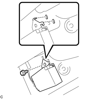
(c) Install the bolt.
Torque:
8.5 N·m {87 kgf·cm, 75 in·lbf}
2. INSTALL ROOF SIDE INNER GARNISH ASSEMBLY LH
HINT:
- Refer to the procedures from "Install roof side inner garnish assembly"
(See page
.gif) ).
). - Installation should be performed only for the left side.
3. CONNECT CABLE TO NEGATIVE BATTERY TERMINAL
NOTICE:
When disconnecting the cable, some systems need to be initialized after the cable
is reconnected (See page ).
4. INSPECT TIRE PRESSURE WARNING SYSTEM
(a) Inspect the tire pressure warning system (See page
).
 Tire Pressure Warning Ecu
Components
COMPONENTS
ILLUSTRATION
ILLUSTRATION
Removal
REMOVAL
CAUTION / NOTICE / HINT
NOTICE:
Before removing the tire pressure warning ECU, read the registered transmitter
IDs of ...

Other materials about Toyota Venza:
Inspection
INSPECTION
PROCEDURE
1. INSPECT REAR POWER WINDOW REGULATOR MOTOR ASSEMBLY LH
(a) Apply positive (+) battery voltage to connector terminal 2 (B).
NOTICE:
Do not apply positive (+) battery voltage to any terminals other than
terminal 2 ( ...
Operation Check
OPERATION CHECK
1. MALFUNCTION BUZZER
(a) Open circuit or frozen
(1) If an open circuit is detected between the ultrasonic sensors and the clearance
warning ECU assembly, if a sensor malfunction is detected or if a sensor is covered
with foreign matter, ...
Installation
INSTALLATION
PROCEDURE
1. INSTALL SEPARATE TYPE FRONT SEAT CUSHION COVER
(a) Using a tacker, install the separate type front seat cushion heater
to the end of the separate type front seat cushion cover with 25 new tack
pins.
NOTICE:
...

0.1402