Toyota Venza: Tire Pressure Warning Ecu
Components
COMPONENTS
ILLUSTRATION
ILLUSTRATION
Removal
REMOVAL
CAUTION / NOTICE / HINT
NOTICE:
Before removing the tire pressure warning ECU, read the registered transmitter
IDs of all wheels and write them down to use for re-registration of transmitter
IDs (See page .gif) ).
).
PROCEDURE
1. DISCONNECT CABLE FROM NEGATIVE BATTERY TERMINAL
NOTICE:
When disconnecting the cable, some systems need to be initialized after the cable
is reconnected (See page ).
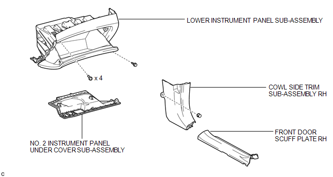
2. REMOVE FRONT DOOR SCUFF PLATE RH
3. REMOVE COWL SIDE TRIM SUB-ASSEMBLY RH
4. REMOVE NO. 2 INSTRUMENT PANEL UNDER COVER SUB-ASSEMBLY
5. REMOVE LOWER INSTRUMENT PANEL SUB-ASSEMBLY
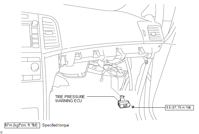
6. REMOVE TIRE PRESSURE WARNING ECU
|
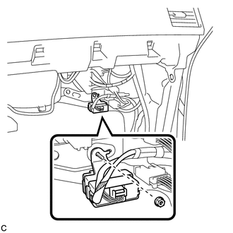
(a) Remove the nut. |
|
|
(b) Disconnect the connector to remove the tire pressure warning ECU. |
|
Installation
INSTALLATION
PROCEDURE
1. INSTALL TIRE PRESSURE WARNING ECU
|
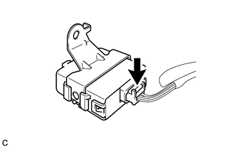
(a) Connect the connector to the tire pressure warning ECU. |
|
.png)
|
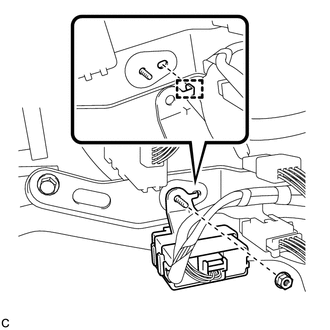
(b) Install the tire pressure warning ECU with the nut. Torque: 8.5 N·m {87 kgf·cm, 75 in·lbf} HINT: Engage the tab into the hole as shown in the illustration to install the tire pressure warning ECU. |
|
2. INSTALL LOWER INSTRUMENT PANEL SUB-ASSEMBLY
.gif)
3. INSTALL NO. 2 INSTRUMENT PANEL UNDER COVER SUB-ASSEMBLY
4. INSTALL COWL SIDE TRIM SUB-ASSEMBLY RH
5. INSTALL FRONT DOOR SCUFF PLATE RH
6. CONNECT CABLE TO NEGATIVE BATTERY TERMINAL
NOTICE:
When disconnecting the cable, some systems need to be initialized after the cable
is reconnected (See page ).
7. REGISTER TRANSMITTER ID
HINT:
It is necessary to register all transmitter IDs (See page
).
8. INSPECT TIRE PRESSURE WARNING SYSTEM
(a) Inspect the tire pressure warning system (See page
).

 Tire Pressure Warning Receiver
Components
COMPONENTS
ILLUSTRATION
Removal
REMOVAL
PROCEDURE
1. DISCONNECT CABLE FROM NEGATIVE BATTERY TERMINAL
NOTICE:
When disconnecting the cable, some systems need to be initialized ...
Other materials about Toyota Venza:
Removal
REMOVAL
CAUTION / NOTICE / HINT
HINT:
Use the same procedure for the RH side and LH side.
The procedure listed below is for the LH side.
PROCEDURE
1. PRECAUTION
CAUTION:
Be sure to read Precaution thoroughly before servicing (See page
...
Under Hood
General Maintenance
GENERAL MAINTENANCE
PROCEDURE
1. GENERAL NOTES
Maintenance requirements vary depending on the country.
Check the maintenance schedule in the owner's manual supplement.
Following the maintenance schedule is mandat ...
Inspection
INSPECTION
PROCEDURE
1. INSPECT NO. 1 ULTRASONIC SENSOR
(a) Measure the resistance according to the value(s) in the table below.
Standard Resistance:
Tester Connection
Condition
Specified ...

0.149