Toyota Venza: Terminals Of Ecu
TERMINALS OF ECU
1. CHECK AWD CONTROL ECU
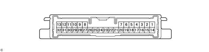
(a) Measure the voltage and resistance of the connector.
|
Terminal No. (Symbol) |
Terminal Description |
Condition |
Specified Condition |
|---|---|---|---|
|
14 (CANH) - 16 (CANL) |
CAN communication |
Ignition switch off |
54 to 69 Ω |
|
23 (GND) - Body ground |
Ground |
Always |
Below 1 Ω |
|
11 (IG1) - 23 (GND) |
Power source voltage |
Ignition switch ON |
10 to 14 V |
|
13 (SLC+) - 32 (SLC-) |
Electromagnetic solenoid signal |
D position, Idling |
Pulse generation (See waveform 1) |
|
9 (BSLC) - 23 (GND) |
Power source voltage |
Always |
10 to 14 V |
If the result is not as specified, the AWD control ECU may have a malfunction.
(b) Using an oscilloscope, check the waveform 1.
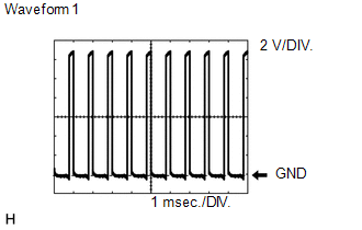 Waveform 1 (Reference)
|
Terminal Name |
Content |
|---|---|
|
Tester Range |
2 V/DIV., 1 msec./DIV. |
|
Condition |
D position, Idling |
 Test Mode Procedure
TEST MODE PROCEDURE
1. DESCRIPTION
HINT:
When using a chassis dynamometer, brake tester, etc. to perform a vehicle test,
activate test mode to avoid a "different tire diameter installed" ...
 Diagnosis System
DIAGNOSIS SYSTEM
1. DESCRIPTION
Active torque control 4WD system data can be read in the Data Link Connector
3 (DLC3) of the vehicle. When the system seems to be malfunctioning, use the Techstream ...
Other materials about Toyota Venza:
Horn System
Precaution
PRECAUTION
NOTICE:
When disconnecting the cable from the negative (-) battery terminal, initialize
the following system after the cable is reconnected.
System Name
See Procedure
Back Door Closer System
...
Engine (ignition) switch (vehicles with smart key system)
Performing the following operations when carrying the electronic key on your
person starts the engine or changes “ENGINE START STOP” switch modes.
- Starting the engine
Check that the parking brake is set.
Check that the shift lever is set
i ...
Terminals Of Ecu
TERMINALS OF ECU
1. COMBINATION METER ASSEMBLY
(a) Measure the voltage and resistance according to the value(s) in the table
below.
Terminal No. (Symbol)
Wiring Color
Terminal Description
Condition
...

0.1482