Toyota Venza: Terminals Of Ecu
TERMINALS OF ECU
1. CHECK AIR CONDITIONING AMPLIFIER ASSEMBLY
(a) Disconnect the D47 air conditioning amplifier assembly connector.
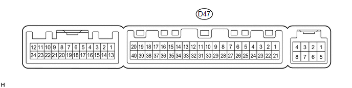
(b) Measure the voltage and resistance according to the value(s) in the table below.
HINT:
Measure the values on the wire harness side with the connector disconnected.
|
Tester Connection |
Wiring Color |
Terminal Description |
Condition |
Specified Condition |
|---|---|---|---|---|
|
D47-1 (IG+) - D47-14 (GND) |
Y - W |
Power source (IG) |
Ignition switch ON |
11 to 14 V |
|
D47-1 (IG+) - D47-14 (GND) |
Y - W |
Power source (IG) |
Ignition switch off |
Below 1 V |
|
D47-21 (B) - D47-14 (GND) |
V - W |
Power source (Back-up) |
Always |
11 to 14 V |
|
D47-14 (GND) - Body ground |
W - Body ground |
Ground |
Always |
Below 1 Ω |
If the result is not as specified, there may be a malfunction in the wire harness.
(c) Reconnect the D47 air conditioning amplifier assembly connector.
(d) Measure the voltage and check for pulses according to the value(s) in the table below.
|
Tester Connection |
Wiring Color |
Terminal Description |
Condition |
Specified Condition |
|---|---|---|---|---|
|
D47-18 (D) - D47-14 (GND) |
G - W |
Rear defogger signal |
Ignition switch ON, rear window defogger switch off |
11 to 14 V |
|
D47-18 (D) - D47-14 (GND) |
G - W |
Rear defogger signal |
Ignition switch ON, rear window defogger switch on |
Below 1 V |
|
D47-37 (LIN1) - D47-14 (GND) |
SB - W |
LIN communication line |
Ignition switch ON |
Pulse generation |
If the result is not as specified, the air conditioning amplifier assembly may have a malfunction.
2. CHECK AIR CONDITIONING CONTROL ASSEMBLY
(a) Disconnect the E3 air conditioning control assembly connector.

(b) Measure the voltage and resistance according to the value(s) in the table below.
HINT:
Measure the values on the wire harness side with the connector disconnected.
|
Tester Connection |
Wiring Color |
Terminal Description |
Condition |
Specified Condition |
|---|---|---|---|---|
|
E3-4 (IG+) - E3-5 (GND) |
GR - W |
Power source (IG) |
Ignition switch ON |
11 to 14 V |
|
E3-4 (IG+) - E3-5 (GND) |
GR - W |
Power source (IG) |
Ignition switch off |
Below 1 V |
|
E3-5 (GND) - Body ground |
W - Body ground |
Ground |
Always |
Below 1 Ω |
If the result is not as specified, there may be a malfunction in the wire harness.
(c) Reconnect the E3 air conditioning control assembly connector.
(d) Check for pulses according to the value(s) in the table below.
|
Tester Connection |
Wiring Color |
Terminal Description |
Condition |
Specified Condition |
|---|---|---|---|---|
|
E3-2 (LIN1) - E3-5 (GND) |
SB - W |
LIN communication line |
Ignition switch ON |
Pulse generation |
If the result is not as specified, the air conditioning control assembly may have a malfunction.
 Problem Symptoms Table
PROBLEM SYMPTOMS TABLE
HINT:
Use the table below to help determine the cause of problem symptoms.
If multiple suspected areas are listed, the potential causes of the symptoms
are lis ...
 Data List / Active Test
DATA LIST / ACTIVE TEST
1. ACTIVE TEST
HINT:
Using the Techstream to perform Active Tests allows relays, VSVs, actuators and
other items to be operated without removing any parts. This non-intrus ...
Other materials about Toyota Venza:
Headlight (HI-BEAM) Circuit
DESCRIPTION
for Halogen Headlight:
The main body ECU (driver side junction block assembly) controls the
high beam headlights.
WIRING DIAGRAM
CAUTION / NOTICE / HINT
NOTICE:
Inspect the fuses for circuits related to this system bef ...
Removal
REMOVAL
PROCEDURE
1. ALIGN FRONT WHEELS FACING STRAIGHT AHEAD
2. DISCONNECT CABLE FROM NEGATIVE BATTERY TERMINAL
NOTICE:
When disconnecting the cable, some systems need to be initialized after the cable
is reconnected (See page ).
3. REMOVE FRONT WHEE ...
Center Airbag Sensor Communication Stop Mode
DESCRIPTION
Detection Item
Symptom
Trouble Area
Center Airbag Sensor Communication Stop Mode
"SRS Airbag" is not displayed on "CAN Bus Check" screen of the
Techs ...

0.1653