Toyota Venza: Television Camera
Components
COMPONENTS
ILLUSTRATION
ILLUSTRATION
Removal
REMOVAL
PROCEDURE
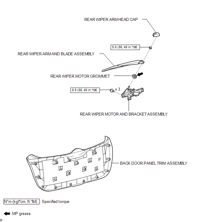
1. REMOVE BACK DOOR PANEL TRIM ASSEMBLY
.gif)
2. REMOVE REAR WIPER ARM HEAD CAP
3. REMOVE REAR WIPER ARM AND BLADE ASSEMBLY
4. REMOVE REAR WIPER MOTOR GROMMET
5. REMOVE REAR WIPER MOTOR AND BRACKET ASSEMBLY
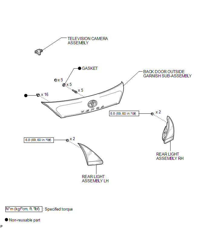
6. REMOVE REAR LIGHT ASSEMBLY LH
7. REMOVE REAR LIGHT ASSEMBLY RH
HINT:
Use the same procedure for the RH side and the LH side (See page
).
8. REMOVE BACK DOOR OUTSIDE GARNISH SUB-ASSEMBLY
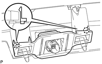
9. REMOVE TELEVISION CAMERA ASSEMBLY
|
(a) Disengage the 2 claws and remove the television camera assembly. |
|
Installation
INSTALLATION
PROCEDURE
1. INSTALL TELEVISION CAMERA ASSEMBLY
|
(a) Engage the 2 claws to install the television camera assembly. |
|
.png)
2. INSTALL BACK DOOR OUTSIDE GARNISH SUB-ASSEMBLY
.gif)
3. INSTALL REAR LIGHT ASSEMBLY RH
HINT:
Use the same procedure for the RH side and the LH side (See page
).
4. INSTALL REAR LIGHT ASSEMBLY LH
5. INSTALL REAR WIPER MOTOR AND BRACKET ASSEMBLY
6. INSTALL REAR WIPER MOTOR GROMMET
7. INSTALL REAR WIPER ARM AND BLADE ASSEMBLY
8. INSTALL REAR WIPER ARM HEAD CAP
9. INSTALL BACK DOOR PANEL TRIM ASSEMBLY
 Image from Camera for Rear View Monitor is Abnormal
DESCRIPTION
The video signal of the rear television camera assembly is transmitted
to the navigation receiver assembly*1 or radio and display receiver assembly*2.
*1: for Navigation Sys ...
 Ultrasonic Sensor(for Front Side)
Components
COMPONENTS
ILLUSTRATION
Removal
REMOVAL
PROCEDURE
1. REMOVE FRONT BUMPER ASSEMBLY
(See page )
2. REMOVE NO. 1 ULTRASONIC SENSOR
(a) Disengage the 2 claws to remov ...
Other materials about Toyota Venza:
Blower Motor Circuit
DESCRIPTION
The blower motor is operated by signals from the A/C amplifier. Blower motor
speed signals are transmitted in accordance with changes in the duty ratio.
WIRING DIAGRAM
CAUTION / NOTICE / HINT
NOTICE:
Inspect the fuses for circuits related ...
Washer fluid
If any washer does not work or the low windshield washer fluid level warning
light comes on, the washer tank may be empty. Add washer fluid.
CAUTION
- When refilling the washer fluid
Do not refill the washer fluid when the engine is hot or running ...
System Description
SYSTEM DESCRIPTION
1. ILLUMINATED ENTRY SYSTEM
(a) The illuminated entry system has the following control functions:
Control
Outline
Lights that Operate
Actuation Area-linked*2
When a registered k ...

0.1687