Toyota Venza: Tcm
Components
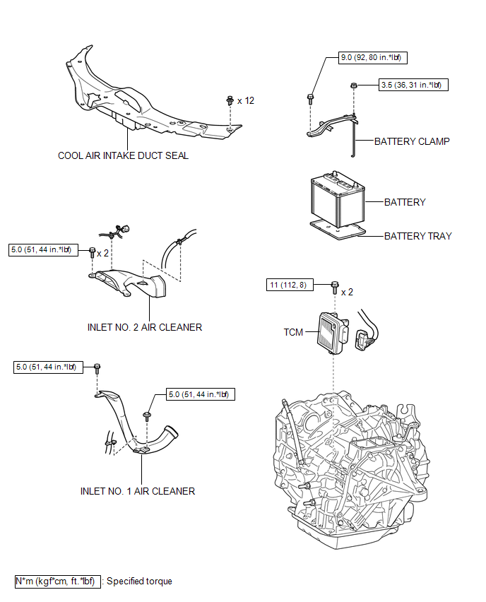
COMPONENTS
ILLUSTRATION
Removal
REMOVAL
CAUTION / NOTICE / HINT
NOTICE:
If automatic transmission parts are replaced, refer to Parts Replacement Compensation
Table to determine if any additional operations are necessary (See page
.gif) ).
).
PROCEDURE
1. DISCONNECT CABLE FROM NEGATIVE BATTERY TERMINAL
NOTICE:
When disconnecting the cable, some systems need to be initialized after the cable
is reconnected (See page ).
2. REMOVE COOL AIR INTAKE DUCT SEAL
3. REMOVE INLET NO. 2 AIR CLEANER
4. REMOVE BATTERY
5. REMOVE INLET NO. 1 AIR CLEANER
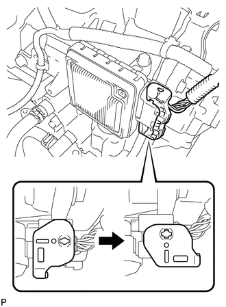
6. REMOVE TCM
|
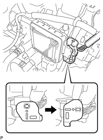
(a) Turn the lock lever and disconnect the connector from the TCM. |
|
|
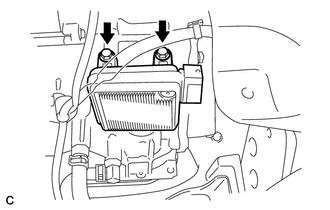
(b) Remove the 2 bolts and TCM from the transaxle. |
|
Installation
INSTALLATION
PROCEDURE
1. INSTALL TCM
(a) Install the TCM to the transaxle.
|
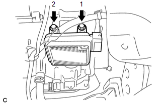
(b) Install and tighten the 2 bolts in the order shown in the illustration. Torque: 11 N·m {112 kgf·cm, 8 ft·lbf} |
|
|
(c) Connect the connector to the TCM. |
|
(d) Turn the lock lever and secure the connector with the lock lever.
2. INSTALL INLET NO. 1 AIR CLEANER
.gif)
3. INSTALL BATTERY
4. INSTALL INLET NO. 2 AIR CLEANER
5. INSTALL COOL AIR INTAKE DUCT SEAL
6. CONNECT CABLE TO NEGATIVE BATTERY TERMINAL
NOTICE:
When disconnecting the cable, some systems need to be initialized after the cable
is reconnected (See page ).
7. CHECK AUTOMATIC TRANSAXLE SYSTEM
NOTICE:
If automatic transmission parts have been replaced, refer to Parts Replacement
Compensation Table to determine if any additional operations are necessary (See
page ).
 Speed Sensor(when Using The Engine Support Bridge)
Components
COMPONENTS
ILLUSTRATION
Removal
REMOVAL
PROCEDURE
1. REMOVE TRANSMISSION VALVE BODY ASSEMBLY
See page
2. REMOVE SPEED SENSOR
(a) Disconnect the speed sensor connector.
...
 Torque Converter And Drive Plate
Inspection
INSPECTION
PROCEDURE
1. INSPECT TORQUE CONVERTER ASSEMBLY
(a) Inspect the one-way clutch.
(1) Press on the serrations of the stator with a finger and rotate it.
Check ...
Other materials about Toyota Venza:
Brake Signal Malfunction (B2284)
DESCRIPTION
The power management control ECU receives brake signal information from 2 sources.
It receives a signal from the stop light switch assembly via a direct line, and
a signal from the ECM via CAN. If the information from these 2 sources is incons ...
Diagnosis System
DIAGNOSIS SYSTEM
1. DESCRIPTION
(a) The power back door ECU (power back door motor unit)*1 or back door closer
ECU (multiplex network door ECU)*2 controls the vehicle's back door closer system
functions. Back door closer system data and Diagnostic Tr ...
Fog Light Assembly
Components
COMPONENTS
ILLUSTRATION
Disassembly
DISASSEMBLY
PROCEDURE
1. REMOVE FOG LIGHT BULB
(a) Turn the fog light bulb in the direction indicated by the arrow shown
in the illustration and remove it.
NOTICE:
Do not touch th ...

0.1565