Toyota Venza: TC and CG Terminal Circuit
DESCRIPTION
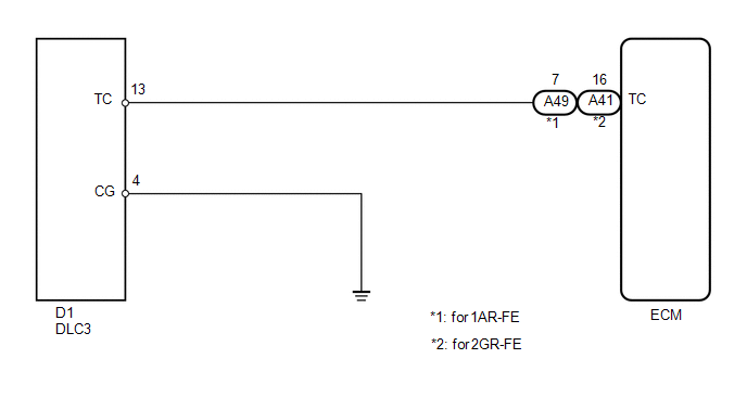
Connecting terminals TC and CG of the DLC3 causes the system to enter self-diagnostic mode. If a malfunction is present, the MIL will blink.
HINT:
When a particular warning light remains blinking, a ground short in the wiring of terminal TC of the DLC3 or an internal ground short in the relevant ECU is suspected.
WIRING DIAGRAM
PROCEDURE
|
1. |
CHECK HARNESS AND CONNECTOR (DLC3 - ECM) |
(a) Disconnect the ECM connector.
(b) Measure the resistance according to the value(s) in the table below.
Standard Resistance:
For 1AR-FE|
Tester Connection |
Condition |
Specified Condition |
|---|---|---|
|
D1-13 (TC) - A49-7 (TC) |
Always |
Below 1 Ω |
|
Tester Connection |
Condition |
Specified Condition |
|---|---|---|
|
D1-13 (TC) - A41-16 (TC) |
Always |
Below 1 Ω |
|
*1 |
DLC3 |
|
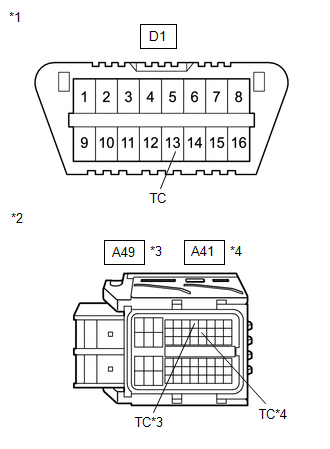
*2 |
Front view of wire harness connector (to ECM) |
|
*3 |
for 1AR-FE |
|
*4 |
for 2GR-FE |
(c) Reconnect the ECM connector.
| NG | .gif) |
REPAIR OR REPLACE HARNESS OR CONNECTOR (DLC3 - ECM) |
|
.gif)
|
2. |
CHECK HARNESS AND CONNECTOR (DLC3 - BODY GROUND) |
(a) Measure the resistance according to the value(s) in the table below.
Standard Resistance:
|
Tester Connection |
Condition |
Specified Condition |
|---|---|---|
|
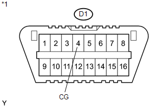
D1-4 (CG) - Body ground |
Always |
Below 1 Ω |
|
*1 |
DLC3 |
| NG | |
REPAIR OR REPLACE HARNESS OR CONNECTOR (DLC3 - BODY GROUND) |
|
|
3. |
CHECK HARNESS AND CONNECTOR (DLC3 - BODY GROUND) |
(a) Measure the resistance according to the value(s) in the table below.
Standard Resistance:
|
Tester Connection |
Condition |
Specified Condition |
|---|---|---|
|
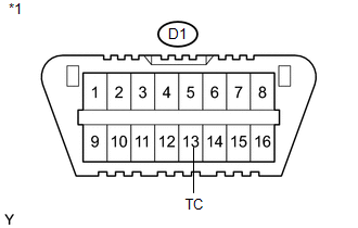
D1-13 (TC) - Body ground |
Always |
10 kΩ or higher |
|
*1 |
DLC3 |
| OK | |
PROCEED TO NEXT SUSPECTED AREA SHOWN IN PROBLEM SYMPTOMS TABLE |
| NG | |
REPAIR OR REPLACE HARNESS OR CONNECTOR OR EACH ECU |
 Cruise SET Indicator Light Circuit
DESCRIPTION
The ECM detects a cruise control switch signal and sends it to the combination
meter assembly through CAN. Then the SET indicator light comes on.
The SET indicator light ci ...

Other materials about Toyota Venza:
Removal
REMOVAL
PROCEDURE
1. REMOVE AUTOMATIC TRANSAXLE ASSEMBLY
HINT:
See the steps from "Remove Engine Assembly with transaxle" through "Remove Automatic
Transaxle Assembly" (See page ).
2. REMOVE AUTOMATIC TRANSAXLE OIL PAN SUB-ASSEMBLY
...
Display does not Dim when Light Control Switch is Turned ON
PROCEDURE
1.
CHECK IMAGE QUALITY SETTING
(a) Turn the light control switch to the tail or head position.
(b) Check that the daytime screen setting on the display adjustment screen is
set to on.
Result
...
Removal
REMOVAL
PROCEDURE
1. REMOVE NO. 1 SLIDING ROOF GLASS SUB-ASSEMBLY
(a) Fully open the No. 2 sliding roof glass sub-assembly.
(b) Using a T20 "TORX" socket wrench, remove the 6 screws and No. 1 sliding
roof glass sub-assembly.
...

0.1356