Toyota Venza: System Diagram
SYSTEM DIAGRAM
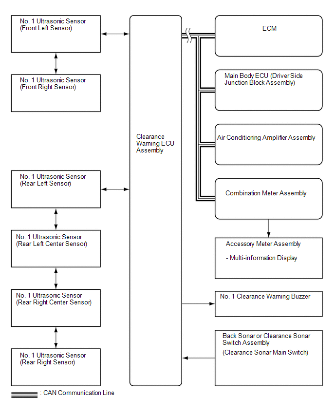 Communication Table
|
Sender |
Receiver |
Signal |
Line |
|---|---|---|---|
|
Main Body ECU (Driver Side Junction Block Assembly) |
Clearance Warning ECU Assembly |
Destination information |
CAN |
|
ECM |
Clearance Warning ECU Assembly |
Shift position |
CAN |
|
Combination Meter Assembly |
Clearance Warning ECU Assembly |
Vehicle speed |
CAN |
|
Air Conditioning Amplifier Assembly |
Clearance Warning ECU Assembly |
Ambient temperature display |
CAN |
|
Clearance Warning ECU Assembly |
Combination Meter Assembly |
|
CAN |
 System Description
SYSTEM DESCRIPTION
1. GENERAL
(a) This system uses ultrasonic sensors to detect any obstacles at the corners
and the rear of the vehicle. The system then informs the driver of the distance
betwe ...
 How To Proceed With Troubleshooting
CAUTION / NOTICE / HINT
HINT:
Use the following procedure to troubleshoot the intuitive parking assist
system.
*: Use the Techstream.
PROCEDURE
1.
VEHI ...
Other materials about Toyota Venza:
Electrical Key Oscillator(for Rear Floor)
Components
COMPONENTS
ILLUSTRATION
Removal
REMOVAL
PROCEDURE
1. REMOVE TONNEAU COVER ASSEMBLY (w/ Tonneau Cover)
2. REMOVE DECK BOARD ASSEMBLY
3. REMOVE NO. 3 DECK BOARD SUB-ASSEMBLY
4. REMOVE DECK SIDE TRIM BOX LH
5. REMOVE NO. 2 D ...
Headlight Signal Circuit
DESCRIPTION
The headlight leveling ECU assembly detects the low beam headlights status.
WIRING DIAGRAM
CAUTION / NOTICE / HINT
NOTICE:
First check that the low beam headlights operate normally.
PROCEDURE
1.
CHECK HARNESS AND CON ...
Removal
REMOVAL
PROCEDURE
1. REMOVE ENGINE ASSEMBLY WITH TRANSAXLE
(a) Remove the engine and transaxle (See page
).
2. REMOVE EXHAUST MANIFOLD CONVERTER SUB-ASSEMBLY
(a) Remove the exhaust manifold converter (See page
).
3. REMOVE THROTTLE BODY ASSEMBLY
...

0.1354