Toyota Venza: System Diagram
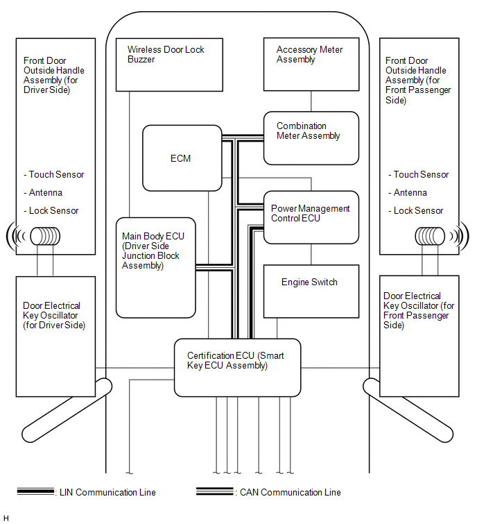
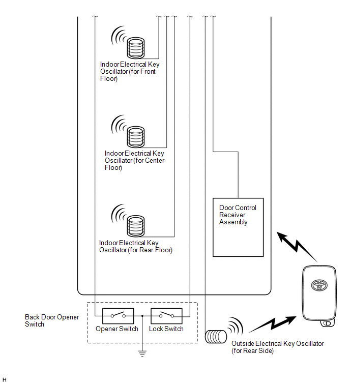
SYSTEM DIAGRAM
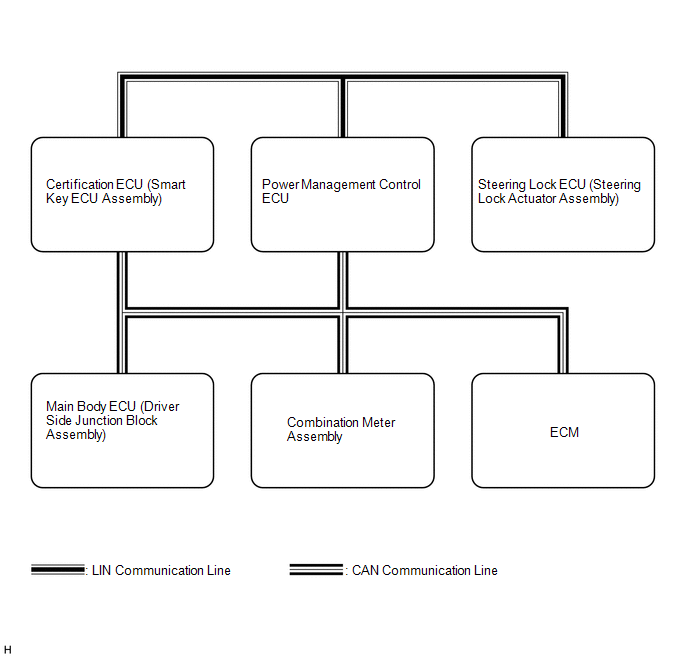
 Communication Table
|
Transmitting ECU (Transmitter) |
Receiving ECU |
Signal |
Communication Method |
|---|---|---|---|
|
Main body ECU (Driver side junction block assembly) |
Certification ECU (Smart key ECU assembly) |
Courtesy light switch signal |
CAN |
|
Door lock output signal |
|||
|
Back door output request signal |
|||
|
Door lock position switch signal |
|||
|
Driver door key operated switch signal |
|||
|
Certification ECU (Smart key ECU assembly) |
Main body ECU (Driver side junction block assembly) |
Illumination light request signal |
CAN |
|
Door lock/unlock request signal |
|||
|
Certification ECU (Smart key ECU assembly) |
Combination meter assembly |
Meter buzzer single tone request signal |
CAN |
|
Meter buzzer intermittent tone request signal |
|||
|
Meter buzzer continuous tone request signal |
|||
|
Key loss warning signal |
|||
|
Low key battery warning signal |
|||
|
Steering lock malfunction warning signal |
|||
|
Steering lock not-released warning signal |
|||
|
Shift position warning signal |
|||
|
Emergency operation support display request signal |
|||
|
Engine start method display request signal |
|||
|
Combination meter assembly |
|
Vehicle speed signal |
CAN |
|
Steering lock ECU (Steering lock actuator assembly) |
Certification ECU (Smart key ECU assembly) |
Encryption code signal |
LIN |
|
Encryption code finish signal |
|||
|
Encryption calculate fixed number memory requirement signal |
|||
|
During entry control signal |
 Parts Location
PARTS LOCATION
ILLUSTRATION
ILLUSTRATION
ILLUSTRATION
ILLUSTRATION
...
 System Description
SYSTEM DESCRIPTION
CAUTION:
If using a pacemaker, be sure to read the manual of the pacemaker before using
the key, as the radio waves of the key may affect the pacemaker.
1. SMART KEY SYSTEM DES ...
Other materials about Toyota Venza:
Fail-safe Chart
FAIL-SAFE CHART
1. Fail-safe
This function minimizes the loss of operation when any abnormality occurs in
a sensor or solenoid.
Fail-safe Control List
Malfunction Part
Function
Input Turbine Speed Sensor
...
Vsc Off Switch
Components
COMPONENTS
ILLUSTRATION
Removal
REMOVAL
PROCEDURE
1. DISCONNECT CABLE FROM NEGATIVE BATTERY TERMINAL
NOTICE:
When disconnecting the cable, some systems need to be initialized after the cable
is reconnected (See page ).
2. REMOVE FR ...
On-vehicle Inspection
ON-VEHICLE INSPECTION
CAUTION / NOTICE / HINT
HINT:
Use the same procedure for the RH side and LH side.
The procedure listed below is for the LH side.
PROCEDURE
1. REMOVE FRONT WHEEL
2. SEPARATE FRONT DISC BRAKE CALIPER ASSEMBLY
3. ...

0.1155