Toyota Venza: System Diagram
SYSTEM DIAGRAM
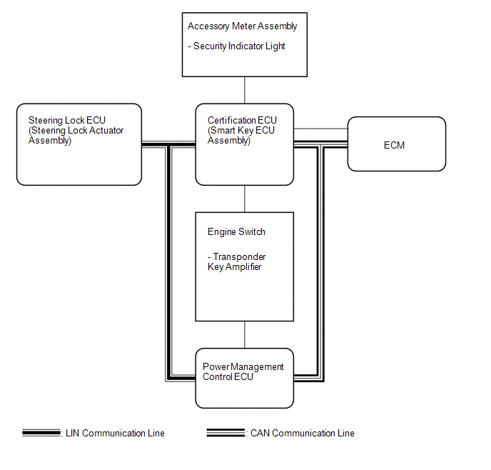 Communication Table
|
Transmitting ECU (Transmitter) |
Receiving ECU (Receiver) |
Signal |
Communication Method |
|---|---|---|---|
|
Certification ECU (smart key ECU assembly) |
Power management control ECU |
Engine immobiliser system set/unset signal |
CAN |
|
Power management control ECU |
Certification ECU (smart key ECU assembly) |
Key code recognition signal |
CAN |
|
Power management control ECU |
Certification ECU (smart key ECU assembly) |
Shift position P signal |
LIN |
|
ID code certification result request signal |
|||
|
Power supply ON operation condition signal |
|||
|
Engine start operation condition signal |
|||
|
ACC relay drive condition signal |
|||
|
Steering lock ECU (Steering lock actuator assembly) |
Certification ECU (Smart key ECU assembly) |
Steering lock signal |
LIN |
|
Steering unlock signal |
|||
|
Steering lock confirmation signal |
|||
|
Steering unlock confirmation signal |
|||
|
Diagnosis response signal |
|||
|
Steering unlock drive relay signal |
|||
|
Steering lock drive relay signal |
|||
|
Steering lock motor operation signal |
|||
|
L code registration status signal |
|||
|
Certification ECU (Smart key ECU assembly) |
Steering lock ECU (Steering lock actuator assembly) |
Steering lock release signal |
LIN |
|
Matching request random number signal |
|||
|
L code registration mode signal |
|||
|
Diagnosis mode request signal |
|||
|
DTC clear request signal |
 Precaution
PRECAUTION
1. PRECAUTION FOR DISCONNECTING CABLE FROM NEGATIVE BATTERY TERMINAL
NOTICE:
When disconnecting the cable from the negative (-) battery terminal, initialize
the following system after ...
 How To Proceed With Troubleshooting
CAUTION / NOTICE / HINT
HINT:
Use the following procedure to troubleshoot the engine immobiliser system.
*: Using the Techstream.
PROCEDURE
1.
VEHICLE B ...
Other materials about Toyota Venza:
Clock Display Circuit
DESCRIPTION
The accessory meter assembly uses this circuit to communicate with the combination
meter assembly via the direct line. The accessory meter assembly uses this circuit
to receive the drive monitor switch signals from the combination meter assemb ...
Inspection
INSPECTION
PROCEDURE
1. INSPECT COMPRESSOR AND MAGNETIC CLUTCH (A/C LOCK SENSOR)
(a) Measure the resistance according to the value(s) in the table below.
Standard Resistance:
Tester Connection
Condition
...
Precaution
PRECAUTION
1. PRECAUTION FOR DISCONNECTING THE BATTERY CABLE
NOTICE:
When disconnecting the cable from the negative (-) battery terminal, initialize
the following systems after the cable is reconnected:
System
See Procedure
...

0.1313