Toyota Venza: System Diagram
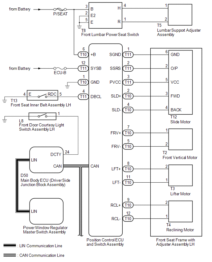
SYSTEM DIAGRAM
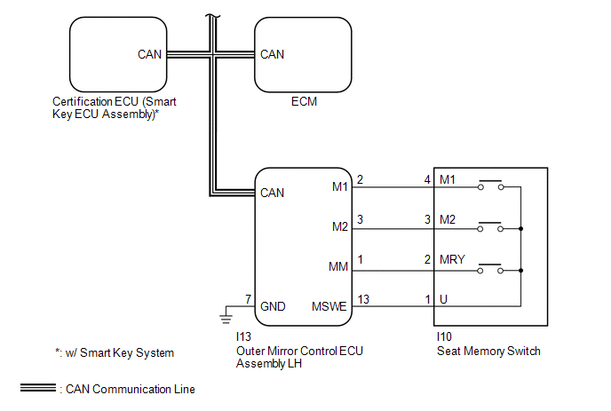 Communication Table
|
Sender |
Receiver |
Signal |
Line |
|---|---|---|---|
|
ECM |
Main Body ECU (Driver Side Junction Block Assembly) |
|
CAN |
|
Outer Mirror Control ECU Assembly LH |
Main Body ECU (Driver Side Junction Block Assembly) |
|
CAN |
|
Main Body ECU (Driver Side Junction Block Assembly) |
Position Control ECU and Switch Assembly |
|
CAN |
|
Certification ECU (Smart Key ECU Assembly)* |
Main Body ECU (Driver Side Junction Block Assembly) |
|
CAN |
|
Position Control ECU and Switch Assembly |
Main Body ECU (Driver Side Junction Block Assembly) |
|
CAN |
- *: w/ Smart Key System
 System Description
SYSTEM DESCRIPTION
1. FRONT POWER SEAT CONTROL SYSTEM DESCRIPTION
The driver seat is equipped with slide, reclining, lifter, front vertical,
and lumbar support adjustment functions.
T ...
 How To Proceed With Troubleshooting
CAUTION / NOTICE / HINT
HINT:
Use the following procedure to troubleshoot the front power seat control
system (w/ Memory).
*: Use the Techstream.
PROCEDURE
1.
...
Other materials about Toyota Venza:
Maintenance requirements
To ensure safe and economical driving, day-to-day care and regular maintenance
is essential. It is the owner’s responsibility to perform regular checks. Toyota
recommends the following maintenance.
- General maintenance
Should be performed on a d ...
Installation
INSTALLATION
PROCEDURE
1. INSTALL REAR DRIVE SHAFT ASSEMBLY
(a) Align the shaft splines and install the rear drive shaft assembly
using a screwdriver and hammer.
NOTICE:
Set the snap ring with the opening facing downward.
...
Security Indicator Light Circuit
DESCRIPTION
The security indicator light blinks continuously due to a continuous signal received
from the certification ECU (smart key ECU assembly) while the engine immobiliser
is set.
WIRING DIAGRAM
CAUTION / NOTICE / HINT
NOTICE:
If the certifica ...

0.1332