Toyota Venza: System Diagram
SYSTEM DIAGRAM
1. MIRROR CONTROL SYSTEM
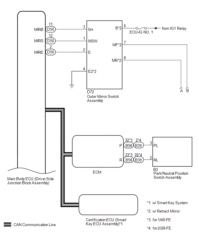
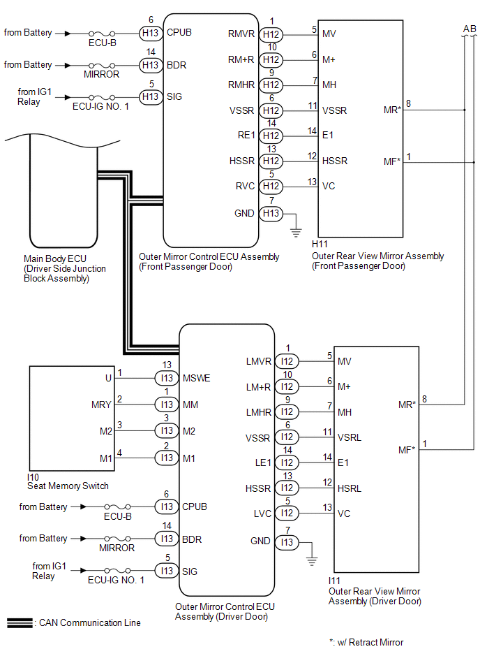 Communication Table
|
Sender |
Receiver |
Signal / Signal Condition |
Line |
|---|---|---|---|
|
Main body ECU (driver side junction block assembly) |
Outer mirror control ECU assembly (driver door) |
Ignition switch signal / ON or off |
CAN |
|
Main body ECU (driver side junction block assembly) |
Outer mirror control ECU assembly (front passenger door) |
Ignition switch signal / ON or off |
CAN |
|
Main body ECU (driver side junction block assembly) |
Outer mirror control ECU assembly (driver door) |
Ignition switch ACC signal / ACC or off |
CAN |
|
Main body ECU (driver side junction block assembly) |
Outer mirror control ECU assembly (front passenger door) |
Ignition switch ACC signal / ACC or off |
CAN |
|
Main body ECU (driver side junction block assembly) |
Outer mirror control ECU assembly (driver door) |
Outer mirror RH select switch signal / on or off |
CAN |
|
Main body ECU (driver side junction block assembly) |
Outer mirror control ECU assembly (front passenger door) |
Outer mirror RH select switch signal / on or off |
CAN |
|
Main body ECU (driver side junction block assembly) |
Outer mirror control ECU assembly (driver door) |
Outer mirror LH select switch signal / on or off |
CAN |
|
Main body ECU (driver side junction block assembly) |
Outer mirror control ECU assembly (front passenger door) |
Outer mirror LH select switch signal / on or off |
CAN |
|
Main body ECU (driver side junction block assembly) |
Outer mirror control ECU assembly (driver door) |
Mirror adjust switch signal (Right) / on or off |
CAN |
|
Main body ECU (driver side junction block assembly) |
Outer mirror control ECU assembly (front passenger door) |
Mirror adjust switch signal (Right) / on or off |
CAN |
|
Main body ECU (driver side junction block assembly) |
Outer mirror control ECU assembly (driver door) |
Mirror adjust switch signal (Left) / on or off |
CAN |
|
Main body ECU (driver side junction block assembly) |
Outer mirror control ECU assembly (front passenger door) |
Mirror adjust switch signal (Left) / on or off |
CAN |
|
Main body ECU (driver side junction block assembly) |
Outer mirror control ECU assembly (driver door) |
Mirror adjust switch signal (Up) / on or off |
CAN |
|
Main body ECU (driver side junction block assembly) |
Outer mirror control ECU assembly (front passenger door) |
Mirror adjust switch signal (Up) / on or off |
CAN |
|
Main body ECU (driver side junction block assembly) |
Outer mirror control ECU assembly (driver door) |
Mirror adjust switch signal (Down) / on or off |
CAN |
|
Main body ECU (driver side junction block assembly) |
Outer mirror control ECU assembly (front passenger door) |
Mirror adjust switch signal (Down) / on or off |
CAN |
|
Main body ECU (driver side junction block assembly) |
Outer mirror control ECU assembly (driver door) |
Mirror position request signal / memory request, reverse memory request, memory call request, reverse request or return request |
CAN |
|
Main body ECU (driver side junction block assembly) |
Outer mirror control ECU assembly (front passenger door) |
Mirror position request signal / memory request, reverse memory request, memory call request, reverse request or return request |
CAN |
|
Outer mirror control ECU assembly (driver door) |
Main body ECU (driver side junction block assembly) |
Outer mirror LH state signal / Manual operation, memory operation, reverse operation or return operation |
CAN |
|
Outer mirror control ECU assembly (front passenger door) |
Main body ECU (driver side junction block assembly) |
Outer mirror RH state signal / Manual operation, memory operation, reverse operation or return operation |
CAN |
|
Outer mirror control ECU assembly (driver door) |
Main body ECU (driver side junction block assembly) |
Seat memory switch signal / M1 switch, M2 switch or SET switch |
CAN |
2. MIRROR HEATER SYSTEM
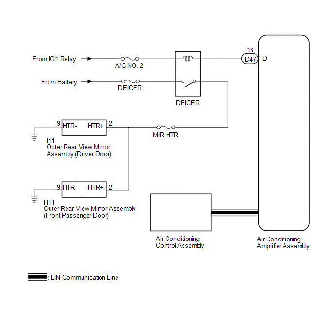 Communication Table
|
Transmitting ECU |
Receiving ECU |
Signal |
Communication Method |
|---|---|---|---|
|
Air Conditioning Control Assembly |
Air Conditioning Amplifier Assembly |
Rear window defogger switch signal |
LIN |
 System Description
SYSTEM DESCRIPTION
1. POWER MIRROR CONTROL SYSTEM DESCRIPTION
(a) This system has the following functions: power retract mirror function*,
reverse shift-linked function, electrical remote control ...
 How To Proceed With Troubleshooting
CAUTION / NOTICE / HINT
HINT:
Use the following procedure to troubleshoot the power mirror control
system.
*: Use the Techstream.
PROCEDURE
1.
VEHICLE ...
Other materials about Toyota Venza:
Air Conditioning Compressor Magnetic Clutch Circuit
DESCRIPTION
When the A/C amplifier is turned on, a magnetic clutch ON signal is sent from
the MGC terminal of the A/C amplifier. Then, the MGC relay turns on to operate the
magnetic clutch.
WIRING DIAGRAM
CAUTION / NOTICE / HINT
NOTICE:
Inspect the ...
Automatic Light Control Sensor
Components
COMPONENTS
ILLUSTRATION
Removal
REMOVAL
PROCEDURE
1. REMOVE DEFROSTER NOZZLE GARNISH
2. REMOVE AUTOMATIC LIGHT CONTROL SENSOR
(a) Disengage the 2 claws and remove the automatic light control sensor.
...
Rear Wheel Alignment
Adjustment
ADJUSTMENT
PROCEDURE
1. INSPECT TIRES
(a) Inspect the tires (See page ).
2. MEASURE VEHICLE HEIGHT
3. INSPECT CAMBER
Camber (Unloaded Vehicle):
Model
Engine
Camber Inclination
Right-left Dif ...

0.1627