Toyota Venza: System Diagram
SYSTEM DIAGRAM
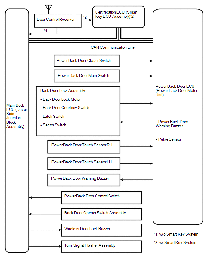 Communication Table
|
Sender |
Receiver |
Signal |
Line |
|---|---|---|---|
|
Main body ECU (Driver side junction block assembly) |
Power back door ECU (Power back door motor unit) |
|
CAN |
|
Power back door ECU (Power back door motor unit) |
Main body ECU (Driver side junction block assembly) |
|
CAN |
|
Certification ECU |
Main body ECU (Driver side junction block assembly) |
Transmitter switch signal |
CAN |
 System Description
SYSTEM DESCRIPTION
1. POWER BACK DOOR SYSTEM DESCRIPTION
(a) The power back door system controls the power back door by automatically
opening and closing the power back door with a motor.
(1) The ...
 How To Proceed With Troubleshooting
CAUTION / NOTICE / HINT
HINT:
Use the following procedures to troubleshoot the power back door system.
*: Use the Techstream.
PROCEDURE
1.
VEHICLE BROUG ...
Other materials about Toyota Venza:
Noise Occurs
PROCEDURE
1.
CHECK NOISE CONDITION
(a) Check from which direction the noise comes (front left or right, or rear
left or right).
OK:
The location of the noise source can be determined.
NG
GO TO STEP 3
...
Diagnosis System
DIAGNOSIS SYSTEM
1. DESCRIPTION
(a) Air conditioning system data and the Diagnostic Trouble Codes (DTCs) can
be read through the Data Link Connector 3 (DLC3) of the vehicle. When the system
seems to be malfunctioning, use the Techstream to check for malf ...
Center Airbag Sensor Assembly Communication Circuit Malfunction (B1790)
DESCRIPTION
The center airbag sensor assembly communication circuit consists of the occupant
classification ECU and center airbag sensor assembly.
DTC B1790 is recorded when a malfunction is detected in the center airbag sensor
assembly communication cir ...

0.1195