Toyota Venza: System Diagram
SYSTEM DIAGRAM
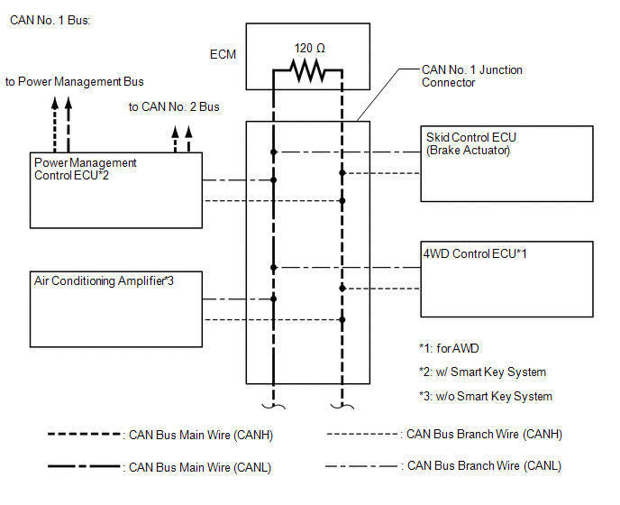
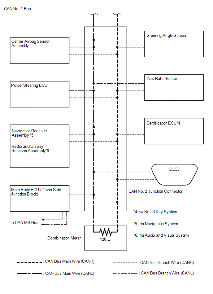
1. CAN NO. 1 BUS
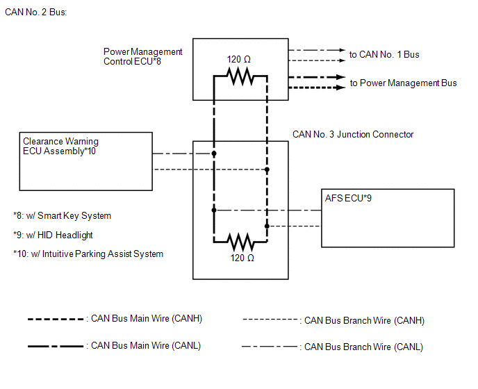
2. CAN NO. 2 BUS
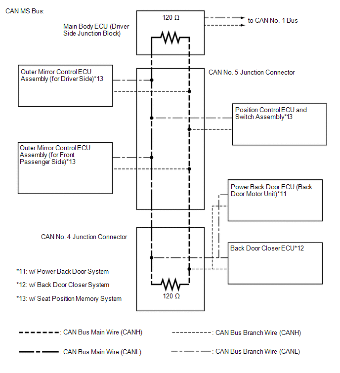
3. CAN MS BUS
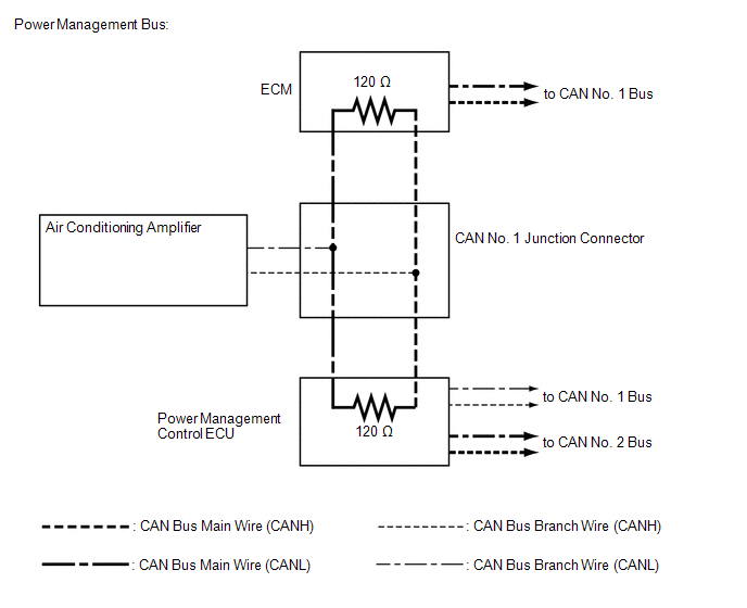
4. POWER MANAGEMENT BUS (w/ Smart Key System)
 Precaution
PRECAUTION
1. PRECAUTION FOR DISCONNECTING BATTERY CABLE
NOTICE:
When disconnecting the cable from the negative (-) battery terminal, initialize
the following systems after the cable is reconnect ...
 How To Proceed With Troubleshooting
CAUTION / NOTICE / HINT
PRECAUTIONS WHEN TROUBLESHOOTING
NOTICE:
DTCs for the CAN communication system are as follows: U0073, U0100,
U0101, U0123, U0124, U0126, U0129, U0131, U0142, U01 ...
Other materials about Toyota Venza:
Disassembly
DISASSEMBLY
PROCEDURE
1. REMOVE BRAKE PEDAL RETURN SPRING
(a) Remove the brake pedal return spring from the brake pedal support
assembly.
2. REMOVE BRAKE PEDAL PAD
(a) Remove the brake pedal pa ...
Seat Position Sensor
Components
COMPONENTS
ILLUSTRATION
On-vehicle Inspection
ON-VEHICLE INSPECTION
CAUTION / NOTICE / HINT
CAUTION:
Be sure to follow the correct removal and installation procedures of the seat
position sensor.
PROCEDURE
1. INSPECT SEAT POSITION S ...
Relay
On-vehicle Inspection
ON-VEHICLE INSPECTION
PROCEDURE
1. INSPECT TAILLIGHT RELAY (TAIL)
(a) Remove the taillight relay from the main body ECU (driver side junction
block assembly).
(b) Measur ...

0.1136