Toyota Venza: Stereo Component Amplifier Disconnected (B15D3)
DESCRIPTION
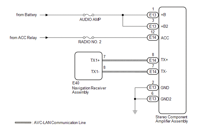
The navigation receiver assembly and stereo component amplifier assembly are connected via AVC-LAN communication.
This DTC is stored when an AVC-LAN communication error occurs between the navigation receiver assembly and stereo component amplifier assembly.
|
DTC No. |
DTC Detection Condition |
Trouble Area |
|---|---|---|
|
B15D3 |
When either of the following conditions is met:
|
|
HINT:
The navigation receiver assembly is the master unit.
WIRING DIAGRAM
CAUTION / NOTICE / HINT
NOTICE:
Inspect the fuses for circuits related to this system before performing the following inspection procedure.
PROCEDURE
|
1. |
CHECK DTC |
(a) If DTC B15C3 is output, perform the troubleshooting for DTC B15C3 first.
|
Result |
Proceed to |
|---|---|
|
DTC B15C3 is not output. |
A |
|
DTC B15C3 is output. |
B |
| B | .gif) |
GO TO DTC B15C3 |
|
.gif)
|
2. |
CHECK OPTIONAL COMPONENTS (INCLUDING ASSOCIATED WIRING) |
(a) Check that optional components (including associated wiring) which generate radio waves are not installed.
|
Result |
Proceed to |
|---|---|
|
Optional components (including associated wiring) are installed. |
A |
|
Optional components (including associated wiring) are not installed. |
B |
HINT:
- Electrical noise from radio waves generated by optional components or the wiring for those components may affect AVC-LAN communication.
- This DTC may be stored when an AVC-LAN communication error occurs due to electrical noise.
| B | |
GO TO STEP 4 |
|
|
3. |
REMOVE OPTIONAL COMPONENTS (INCLUDING ASSOCIATED WIRING) |
(a) Remove optional components (including associated wiring).
NOTICE:
Do not remove optional components or associated wiring without the permission of the customer.
|
|
4. |
CHECK DTC |
(a) Clear the DTCs (See page .gif) ).
).
(b) Recheck for DTCs and check that no DTCs are output.
OK:
No DTCs are output.
| OK | |
END |
|
|
5. |
CHECK HARNESS AND CONNECTOR (STEREO COMPONENT AMPLIFIER ASSEMBLY POWER SOURCE) |
(a) Disconnect the E13 and E14 stereo component amplifier assembly connectors.
(b) Measure the resistance according to the value(s) in the table below.
Standard Resistance:
|
Tester Connection |
Condition |
Specified Condition |
|---|---|---|
|
E13-2 (GND) - Body ground |
Always |
Below 1 Ω |
|
E13-6 (GND2) - Body ground |
Always |
Below 1 Ω |
(c) Measure the voltage according to the value(s) in the table below.
Standard Voltage:
|
Tester Connection |
Condition |
Specified Condition |
|---|---|---|
|
E13-1 (+B) - E13-2 (GND) |
Always |
11 to 14 V |
|
E13-3 (+B2) - E13-2 (GND) |
Always |
11 to 14 V |
|
E14-12 (ACC) - E13-2 (GND) |
Ignition switch ACC |
11 to 14 V |
| NG | |
REPAIR OR REPLACE HARNESS OR CONNECTOR |
|
|
6. |
CHECK HARNESS AND CONNECTOR (NAVIGATION RECEIVER ASSEMBLY - STEREO COMPONENT AMPLIFIER ASSEMBLY) |
(a) Disconnect the E40 navigation receiver assembly connector.
(b) Disconnect the E14 stereo component amplifier assembly connector.
(c) Measure the resistance according to the value(s) in the table below.
Standard Resistance:
|
Tester Connection |
Condition |
Specified Condition |
|---|---|---|
|
E40-7 (TX1+) - E14-8 (TX+) |
Always |
Below 1 Ω |
|
E40-8 (TX1-) - E14-7 (TX-) |
Always |
Below 1 Ω |
|
E40-7 (TX1+) - Body ground |
Always |
10 kΩ or higher |
|
E40-8 (TX1-) - Body ground |
Always |
10 kΩ or higher |
| NG | |
REPAIR OR REPLACE HARNESS OR CONNECTOR |
|
|
7. |
REPLACE STEREO COMPONENT AMPLIFIER ASSEMBLY |
(a) Replace the stereo component amplifier assembly with a new or known good
one (See page ).
(b) Clear the DTCs (See page ).
(c) Recheck for DTCs and check that no DTCs are output.
OK:
No DTCs are output.
| OK | |
END |
| NG | |
REPLACE NAVIGATION RECEIVER ASSEMBLY |
 Speaker Output Short (B15C3)
DESCRIPTION
This DTC is stored when a malfunction occurs in the speakers.
DTC No.
DTC Detection Condition
Trouble Area
B15C3
A short is d ...
 A/C ECU Vehicle Information Reading/Writing Processor Malfunction (B15F5)
DESCRIPTION
This DTC is stored when items controlled by the air conditioning amplifier assembly
cannot be customized via the navigation system vehicle customization screen.
HINT:
The air conditio ...
Other materials about Toyota Venza:
Removal
REMOVAL
PROCEDURE
1. DISCHARGE FUEL SYSTEM PRESSURE
HINT:
See page
2. DISCONNECT CABLE FROM NEGATIVE BATTERY TERMINAL
NOTICE:
When disconnecting the cable, some systems need to be initialized after the cable
is reconnected (See page ).
3. REMOVE W ...
Clearance Sonar Main Switch Circuit
DESCRIPTION
The back sonar or clearance sonar switch assembly is installed at the base of
the driver side of the instrument panel.
When the clearance sonar main switch is turned on, an on signal is sent to the
clearance warning ECU assembly. The intuitiv ...
Removal
REMOVAL
PROCEDURE
1. REMOVE FRONT SEAT ASSEMBLY LH
(See page )
2. REMOVE FRONT DOOR SCUFF PLATE LH
3. REMOVE COWL SIDE TRIM SUB-ASSEMBLY LH
4. REMOVE FRONT DOOR OPENING TRIM WEATHERSTRIP LH
5. REMOVE REAR DOOR SCUFF PLATE LH
6. REMOVE REAR ...

0.1452