Toyota Venza: Steering Lock Motor Drive Power Circuit
DESCRIPTION
The steering lock ECU (steering lock actuator assembly) is connected to the power management control ECU. The steering lock ECU (steering lock actuator assembly) cannot activate the motor unless it receives permission signals from both ECUs. (The power management control ECU permits the steering lock ECU (steering lock actuator assembly) to supply power to activate the motor.)
WIRING DIAGRAM
.png)
PROCEDURE
|
1. |
CHECK VEHICLE CONDITION |
(a) Check the problem symptom of the steering lock system.
|
Condition |
Proceed to |
|---|---|
|
Steering lock cannot be released. |
A |
|
Steering cannot be locked. |
B |
| B | .gif) |
GO TO STEP 6 |
|
.gif)
|
2. |
READ VALUE USING TECHSTREAM |
(a) Connect the Techstream to the DLC3.
(b) Turn the engine switch on (IG).
(c) Turn the Techstream on.
(d) Check the steering lock command reception record. Enter the following menus: Body Electrical / Smart Key / Data List.
Smart Key|
Tester Display |
Measurement Item/Range |
Normal Condition |
Diagnostic Note |
|---|---|---|---|
|
Lock/Unlock Receive |
Steering lock command reception record / Yes or No |
Yes: Steering lock/unlock signal received No: Steering lock/unlock signal not received |
- |
(e) Check if steering unlock command reception is confirmed.
OK:
"YES" is displayed on the Techstream.
| NG | |
CHECK SMART KEY SYSTEM (for Start Function) |
|
|
3. |
INSPECT STEERING LOCK ECU (STEERING LOCK ACTUATOR ASSEMBLY) |
|
(a) Measure the voltage according to the value(s) in the table below. Standard Voltage:
|
|
.png)
|
*1 |
Component with harness connected (Steering Lock ECU (Steering Lock Actuator Assembly)) |
| OK | |
PROCEED TO NEXT CIRCUIT INSPECTION SHOWN IN PROBLEM SYMPTOMS TABLE |
|
|
4. |
CHECK HARNESS AND CONNECTOR (STEERING LOCK ECU - BODY GROUND) |
|
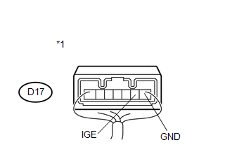
(a) Disconnect the D17 connector from the steering lock ECU (steering lock actuator assembly). |
|
.png)
(b) Measure the resistance according to the value(s) in the table below.
Standard Resistance:
|
Tester Connection |
Condition |
Specified Condition |
|---|---|---|
|
D17-1 (GND) - Body ground |
Always |
Below 1 Ω |
|
*1 |
Front view of wire harness connector (to Steering Lock ECU (Steering Lock Actuator Assembly)) |
| NG | |
REPAIR OR REPLACE HARNESS OR CONNECTOR |
|
|
5. |
CHECK HARNESS AND CONNECTOR (STEERING LOCK ECU - POWER MANAGEMENT CONTROL ECU) |
|
(a) Disconnect the D43 connector from the power management control ECU. |
|
.png)
(b) Measure the resistance according to the value(s) in the table below.
Standard Resistance:
|
Tester Connection |
Condition |
Specified Condition |
|---|---|---|
|
D17-3 (IGE) - D43-8 (SLR+) |
Always |
Below 1 Ω |
|
D17-3 (IGE) - Body ground |
Always |
10 kΩ or higher |
|
*1 |
Front view of wire harness connector (to Steering Lock ECU (Steering Lock Actuator Assembly)) |
|
*2 |
Front view of wire harness connector (to Power Management Control ECU) |
| OK | |
REPLACE POWER MANAGEMENT CONTROL ECU |
| NG | |
REPAIR OR REPLACE HARNESS OR CONNECTOR |
|
6. |
INSPECT STEERING LOCK ECU (STEERING LOCK ACTUATOR ASSEMBLY) |
|
(a) Measure the voltage according to the value(s) in the table below. Standard Voltage:
|
|
|
*1 |
Component with harness connected (Steering Lock ECU (Steering Lock Actuator Assembly)) |
| OK | |
PROCEED TO NEXT SUSPECTED AREA SHOWN IN PROBLEM SYMPTOMS TABLE |
|
|
7. |
CHECK HARNESS AND CONNECTOR (STEERING LOCK ECU - POWER MANAGEMENT CONTROL ECU) |
|
(a) Disconnect the D17 connector from the steering lock ECU (steering lock actuator assembly). |
|
(b) Disconnect the D43 connector from the power management control ECU.
(c) Measure the resistance according to the value(s) in the table below.
Standard Resistance:
|
Tester Connection |
Condition |
Specified Condition |
|---|---|---|
|
D17-3 (IGE) - D43-8 (SLR+) |
Always |
Below 1 Ω |
|
D17-3 (IGE) - Body ground |
Always |
10 kΩ or higher |
|
*1 |
Front view of wire harness connector (to Steering Lock ECU (Steering Lock Actuator Assembly)) |
|
*2 |
Front view of wire harness connector (to Power Management Control ECU) |
| OK | |
REPLACE POWER MANAGEMENT CONTROL ECU |
| NG | |
REPAIR OR REPLACE HARNESS OR CONNECTOR |
 Open / Short in Steering Lock ECU (B2781)
DESCRIPTION
If the steering lock ECU (steering lock actuator assembly) determines that there
is a malfunction inside the ECU, it outputs this DTC. Diagnostic communication between
the steering lo ...
 Unlock Position Sensor Signal Circuit
DESCRIPTION
The unlock position sensor is one of the components comprising the steering lock
ECU (steering lock actuator assembly). The sensor switch contact closes when the
steering lock is rele ...
Other materials about Toyota Venza:
Torque Converter Clutch Solenoid Performance (Shift Solenoid Valve SL) (P0741)
SYSTEM DESCRIPTION
The TCM uses signals from the throttle position sensor, air-flow meter, turbine
(input) speed sensor, intermediate (counter gear) speed sensor and crankshaft position
sensor to help determine the engagement timing of the lock-up clutch. ...
Power Source Mode does not Change to ON (IG and ACC)
DESCRIPTION
When the engine switch is pushed with the electrical key in the cabin, the power
management control ECU receives signals to change the power source mode.
HINT:
To allow use of the Techstream to inspect the push-button start function when
the ...
Wireless Door Lock Tuner Circuit Malfunction (B1242)
DESCRIPTION
The door control receiver is used to receive electrical waves relating to the
entry functions of the smart key system. The certification ECU (smart key ECU assembly)
decodes the requested smart key system operation by identifying a key code ba ...

0.125