Toyota Venza: Steering Angle Sensor Circuit Malfunction (C1231/31)
DESCRIPTION
The steering angle sensor signal is sent to the skid control ECU via the CAN communication system. When there is a malfunction in the CAN communication system, it will be detected by the steering angle sensor zero point malfunction diagnostic function.
|
DTC Code |
DTC Detection Condition |
Trouble Area |
|---|---|---|
|
C1231/31 |
When ECU IG1 terminal voltage is 9.5 V or more, the steering angle sensor malfunction signal is received. |
|
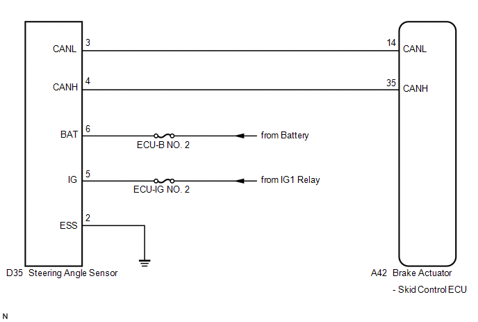
WIRING DIAGRAM
CAUTION / NOTICE / HINT
HINT:
- When U0073/94, U0123/62 and/or U0126/63 is output together with C1231/31,
inspect and repair the trouble areas indicated by U0073/94, U0123/62 and/or
U0126/63 first (See page
.gif) ).
). - When the speed sensor or the yaw rate and acceleration sensor has trouble, DTCs for the steering angle sensor may be output even when the steering angle sensor is normal. When DTCs for the speed sensor or yaw rate and acceleration sensor are output together with other DTCs for the steering angle sensor, inspect and repair the speed sensor and yaw rate and acceleration sensor first, and then inspect and repair the steering angle sensor.
PROCEDURE
|
1. |
CHECK DTC |
(a) Clear the DTCs (See page ).
(b) Turn the ignition switch off.
(c) Turn the ignition switch to ON again and check that no CAN communication
system DTC is output (See page ).
(d) Drive the vehicle and turn the steering wheel to the right and left at a
speed of 35 km/h (22 mph) and check that no speed sensor and yaw rate and acceleration
sensor DTCs are output (See page ).
|
Result |
Proceed to |
|---|---|
|
No CAN communication system DTC and the speed sensor or yaw rate and acceleration sensor DTC are output |
A |
|
CAN communication system DTC is output |
B |
|
Speed sensor or yaw rate and acceleration sensor DTC is output |
C |
HINT:
- If there is a malfunction in the speed sensor or the yaw rate and acceleration sensor, an abnormal value may be output although the steering angle sensor is normal.
- If the speed sensor and the yaw rate and acceleration sensor DTCs are output simultaneously, repair the sensors and inspect the steering angle sensor.
| B | .gif) |
INSPECT CAN COMMUNICATION SYSTEM |
| C | |
REPAIR CIRCUITS INDICATED BY OUTPUT DTCS |
|
.gif)
|
2. |
INSPECT STEERING ANGLE SENSOR (POWER SOURCE TERMINAL) |
|
(a) Turn the ignition switch off. |
|
(b) Remove the steering wheel and the column cover.
(c) Make sure that there is no looseness at the locking part and the connecting part of the connector.
(d) Disconnect the steering angle sensor connector.
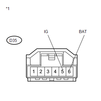
(e) Measure the voltage according to the value(s) in the table below.
Standard Voltage:
|
Tester Connection |
Condition |
Specified Condition |
|---|---|---|
|
D35-5 (IG) - Body ground |
Ignition switch ON |
11 to 14 V |
|
D35-6 (BAT) - Body ground |
Always |
11 to 14 V |
|
*1 |
Front view of wire harness connector (to Spiral Cable Sub-assembly (Steering Angle Sensor)) |
| NG | |
REPAIR OR REPLACE HARNESS OR CONNECTOR (POWER SOURCE CIRCUIT) |
|
|
3. |
INSPECT STEERING ANGLE SENSOR (GROUND TERMINAL) |
|
(a) Turn the ignition switch off. |
|
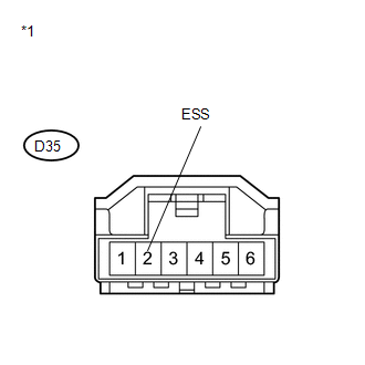
(b) Measure the resistance according to the value(s) in the table below.
Standard Resistance:
|
Tester Connection |
Condition |
Specified Condition |
|---|---|---|
|
D35-2 (ESS) - Body ground |
Always |
Below 1 Ω |
|
*1 |
Front view of wire harness connector (to Spiral Cable Sub-assembly (Steering Angle Sensor)) |
HINT:
If troubleshooting has been carried out according to Problem Symptoms Table,
refer back to the table and proceed to the next step (See page
).
| OK | |
REPLACE SPIRAL CABLE SUB-ASSEMBLY (STEERING ANGLE SENSOR) |
| NG | |
REPAIR OR REPLACE HARNESS OR CONNECTOR (GROUND CIRCUIT) |
 Low Battery Positive Voltage or Abnormally High Battery Positive Voltage (C1241/41)
DESCRIPTION
If a malfunction is detected in the power supply circuit, the skid control ECU
(housed in the actuator assembly) stores this DTC and the fail-safe function prohibits
ABS operation.
T ...
 Malfunction in Deceleration Sensor (C0365/28,C1234/34,C1245/32,C1245/45)
DESCRIPTION
The skid control ECU receives signals from the yaw rate and acceleration sensor
via the CAN communication system.
The yaw rate sensor has a built-in acceleration sensor.
If there is t ...
Other materials about Toyota Venza:
No Signal from Transmitter ID1 (C2121/21-C2124/24,C2181/81-C2184/84)
DESCRIPTION
The tire pressure warning valve and transmitter installed in each tire and wheel
assembly measures the tire pressures. The measured values are transmitted as radio
waves to the tire pressure warning antenna and receiver on the body and then se ...
Power back door switch (vehicles with power back door)
Push the switch to close.
Pressing the switch again while the power back door is closing will cause it
to open again.
However, the reverse operation cannot be performed for the first second after
pressing the switch to close the door.
The back door ca ...
Inspection
INSPECTION
PROCEDURE
1. INSPECT GENERATOR CLUTCH PULLEY
(a) Hold the generator rotor using SST, and turn the clutch pulley clockwise
to check that the outer ring locks.
SST: 09820-63021
Text in Illustration
*1
...

0.161