Toyota Venza: Slip Indicator Light Remains ON
DESCRIPTION
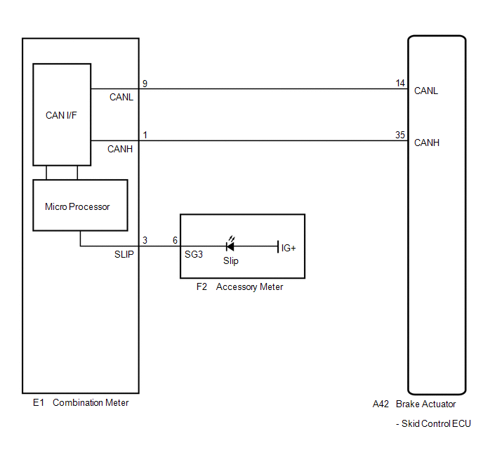
The skid control ECU is connected to the combination meter via CAN communication.
The slip indicator light blinks during VSC and/or TRAC operation.
When the system fails, the slip indicator light comes on to warn the driver (See
page .gif) ).
).
WIRING DIAGRAM
PROCEDURE
|
1. |
CHECK CAN COMMUNICATION SYSTEM |
(a) Check if a CAN communication system DTC is output (See page
).
|
Result |
Proceed to |
|---|---|
|
DTC is not output |
A |
|
DTC is output |
B |
| B | .gif) |
INSPECT CAN COMMUNICATION SYSTEM |
|
.gif)
|
2. |
CHECK IF SKID CONTROL ECU CONNECTOR IS SECURELY CONNECTED |
(a) Check if the skid control ECU connector is securely connected.
OK:
The connector is securely connected.
| NG | |
CONNECT CONNECTOR TO ECU CORRECTLY |
|
|
3. |
CHECK BATTERY |
(a) Check the battery voltage.
Standard voltage:
11 to 14 V
|
Result |
Proceed to |
|---|---|
|
OK |
A |
|
NG (for 2GR-FE) |
B |
|
NG (for 1AR-FE) |
C |
| B | |
CHECK OR REPLACE CHARGING SYSTEM OR BATTERY (for 2GR-FE) |
| C | |
CHECK OR REPLACE CHARGING SYSTEM OR BATTERY (for 1AR-FE) |
|
|
4. |
INSPECT COMBINATION METER ASSEMBLY |
(a) Turn the ignition switch to ON and check the slip indicator light will come on for approximately 3 seconds (initial check).
(b) Perform the Active Test of the combination meter (meter CPU) using the Techstream
(See page ).
(c) Check the accessory meter.
|
Result |
Proceed to |
|---|---|
|
OK |
A |
|
NG (Initial check is normal, and the slip indicator light does not turn on or off in accordance with the Techstream operation) |
B |
|
NG (Initial check is abnormal) |
C |
HINT:
If troubleshooting has been carried out according to Problem Symptoms Table,
refer back to the table and proceed to the next step before replacing the part (See
page ).
| A | |
REPLACE BRAKE ACTUATOR ASSEMBLY |
| B | |
REPLACE COMBINATION METER ASSEMBLY |
| C | |
REPLACE ACCESSORY METER ASSEMBLY |
 Slip Indicator Light does not Come ON
DESCRIPTION
The skid control ECU is connected to the combination meter via CAN communication.
WIRING DIAGRAM
Refer to Slip Indicator Light Remains ON (See page
).
PROCEDURE
1.
...
 TC and CG Terminal Circuit
DESCRIPTION
Connecting terminals TC and CG of the DLC3 causes the ECU to display the DTC
by blinking the ABS warning and slip indicator lights.
WIRING DIAGRAM
CAUTION / NOTICE / HINT
HINT:
Wh ...
Other materials about Toyota Venza:
Radio Receiver Power Source Circuit
DESCRIPTION
This is the power source circuit to operate the radio and display receiver assembly.
WIRING DIAGRAM
CAUTION / NOTICE / HINT
NOTICE:
Inspect the fuses for circuits related to this system before performing the following
inspection procedure. ...
Transfer Case Front Oil Seal(when Using The Engine Support Bridge)
Components
COMPONENTS
ILLUSTRATION
Replacement
REPLACEMENT
PROCEDURE
1. REMOVE TRANSFER ASSEMBLY
See page
2. REMOVE TRANSFER CASE FRONT OIL SEAL
(a) Using SST, remove the transfer case front oil seal from the transfer
case.
S ...
Dtc Check / Clear
DTC CHECK / CLEAR
HINT:
Use the Techstream to read and clear the DTC of the occupant classification ECU,
otherwise the DTCs cannot be read and cleared.
1. DTC CHECK
(a) Turn the ignition switch off.
(b) Connect the Techstream to the DLC3.
(c) Turn the ...

0.132