Toyota Venza: Security Indicator Light Circuit
DESCRIPTION
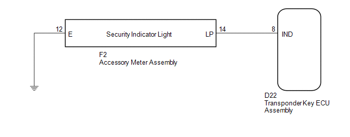
The security indicator light blinks continuously due to a continuous signal received from the transponder key ECU assembly while in the armed state.
WIRING DIAGRAM
CAUTION / NOTICE / HINT
NOTICE:
If the transponder key ECU assembly is replaced, register the key and ECU communication
ID (See page .gif) ).
).
PROCEDURE
|
1. |
PERFORM ACTIVE TEST USING TECHSTREAM |
(a) Connect the Techstream to the DLC3.
(b) Turn the ignition switch to ON.
(c) Turn the Techstream on.
(d) Enter the following menus: Body Electrical / Immobiliser / Active Test.
(e) Perform the Active Test according to the display on the Techstream.
Immobiliser (Transponder Key ECU Assembly)|
Tester Display |
Test Part |
Control Range |
Diagnostic Note |
|---|---|---|---|
|
Security Indicator |
Security indicator light |
ON/OFF |
- |
OK:
The security indicator turns on and off according to operation via the Techstream.
| OK | .gif) |
REPLACE TRANSPONDER KEY ECU ASSEMBLY |
|
.gif)
|
2. |
CHECK HARNESS AND CONNECTOR (TRANSPONDER KEY ECU - ACCESSORY METER) |
(a) Disconnect the transponder key ECU assembly connector.
|
(b) Disconnect the accessory meter assembly connector. |
|
(c) Measure the resistance according to the value(s) in the table below.
Standard Resistance:
|
Tester Connection |
Condition |
Specified Condition |
|---|---|---|
|
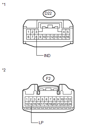
D22-8 (IND) - F2-14 (LP) |
Always |
Below 1 Ω |
|
D22-8 (IND) - Body ground |
Always |
10 kΩ or higher |
|
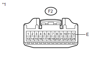
F2-14 (LP) - Body ground |
Always |
10 kΩ or higher |
|
*1 |
Front view of wire harness connector (to Transponder Key ECU Assembly) |
|
*2 |
Front view of wire harness connector (to Accessory Meter Assembly) |
| NG | |
REPAIR OR REPLACE HARNESS OR CONNECTOR |
|
|
3. |
CHECK HARNESS AND CONNECTOR (ACCESSORY METER - BODY GROUND) |
|
(a) Measure the resistance according to the value(s) in the table below. Standard Resistance:
|
|
| OK | |
REPLACE ACCESSORY METER ASSEMBLY |
| NG | |
REPAIR OR REPLACE HARNESS OR CONNECTOR |
 Door Courtesy Switch Circuit
DESCRIPTION
When an additional transponder key is registered, the transponder key ECU assembly
detects the front door courtesy light switch assembly (for driver side) open/close
condition, and en ...
 ECU Power Source Circuit
DESCRIPTION
This circuit provides power to operate the transponder key ECU assembly.
WIRING DIAGRAM
CAUTION / NOTICE / HINT
NOTICE:
If the transponder key ECU assembly is replaced, register the ...
Other materials about Toyota Venza:
If your vehicle overheats
The following may indicate that your vehicle is overheating.
• The engine coolant temperature gauge reaches the maximum, or a loss of
engine power is experienced. (For example, the vehicle speed does not increase.)
• Steam comes out from under the hood ...
Locking the driver’s doors from the outside without a key
Move the inside lock button to the
lock position.
Close the door.
►Vehicles with smart key system
The door cannot be locked if the “ENGINE START STOP” switch is in ACCESSORY or IGNITION
ON mode, or the electronic key is left inside the vehic ...
Steering Lock Motor Drive Power Circuit
DESCRIPTION
The steering lock ECU (steering lock actuator assembly) is connected to the power
management control ECU. The steering lock ECU (steering lock actuator assembly)
cannot activate the motor unless it receives permission signals from both ECUs.
...

0.1147