Toyota Venza: Security Horn Circuit
DESCRIPTION
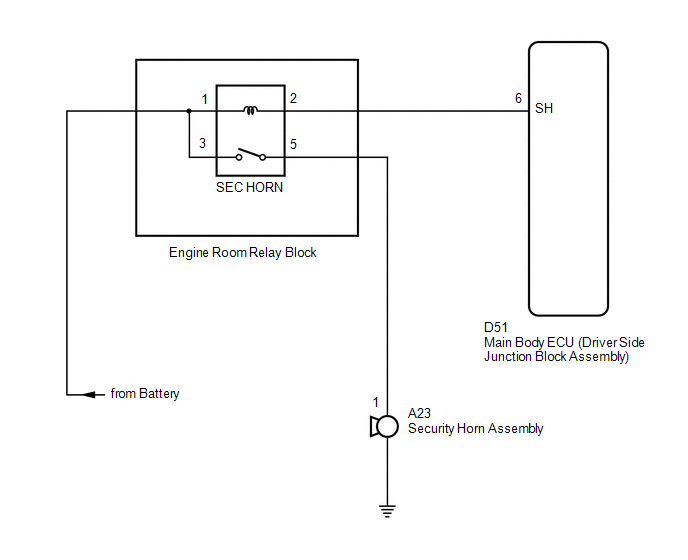
When the theft deterrent system is switched from the armed state to the alarm sounding state, the main body ECU (driver side junction block assembly) controls the security horn.
WIRING DIAGRAM
PROCEDURE
|
1. |
PERFORM ACTIVE TEST USING TECHSTREAM |
(a) Connect the Techstream to the DLC3.
(b) Turn the engine switch on (IG).
(c) Turn the Techstream on.
(d) Select the item below in the Active Test and then check that the security horn assembly operates.
Body|
Tester Display |
Test Part |
Control Range |
Diagnostic Note |
|---|---|---|---|
|
Security Horn |
Security horn |
ON/OFF |
- |
OK:
The security horn assembly sounds and stops correctly when operated through the Techstream.
| OK | .gif) |
PROCEED TO NEXT SUSPECTED AREA SHOWN IN PROBLEM SYMPTOMS TABLE |
|
.gif)
|
2. |
INSPECT SECURITY HORN ASSEMBLY |
|
(a) Remove the security horn assembly (See page
|
|
.gif) ).
)..png)
(b) Check the operation of the security horn assembly.
OK:
|
Measurement Condition |
Specified Condition |
|---|---|
|
Battery positive (+) → Terminal 1 |
Horn sounds |
|
Battery negative (-) → Horn body |
| NG | |
REPLACE SECURITY HORN ASSEMBLY |
|
|
3. |
INSPECT SEC HORN RELAY |
|
(a) Remove the SEC HORN relay from the engine room relay block. |
|
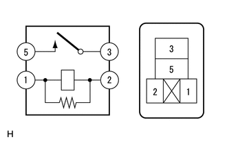
(b) Measure the resistance according to the value(s) in the table below.
Standard Resistance:
|
Tester Connection |
Condition |
Specified Condition |
|---|---|---|
|
3 - 5 |
Battery voltage applied to terminals 1 and 2 |
Below 1 Ω |
|
3 - 5 |
Battery voltage not applied between terminals 1 and 2 |
10 kΩ or higher |
| NG | |
REPLACE SEC HORN RELAY |
|
|
4. |
CHECK HARNESS AND CONNECTOR (SEC HORN RELAY POWER SOURCE) |
|
(a) Measure the voltage according to the value(s) in the table below. Standard Voltage:
|
|
| NG | |
REPAIR OR REPLACE HARNESS OR CONNECTOR |
|
|
5. |
CHECK HARNESS AND CONNECTOR (SEC HORN RELAY - MAIN BODY ECU) |
|
(a) Disconnect the D51 main body ECU (driver side junction block assembly) connector. |
|
(b) Measure the resistance on the relay block side according to the value(s) in the table below.
Standard Resistance:
|
Tester Connection |
Condition |
Specified Condition |
|---|---|---|
|
Engine room relay block SEC HORN relay terminal 1 - D51-6 (SH) |
Always |
Below 1 Ω |
|
Engine room relay block SEC HORN relay terminal 1 - Body ground |
Always |
10 kΩ or higher |
|
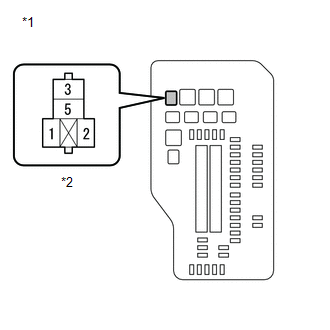
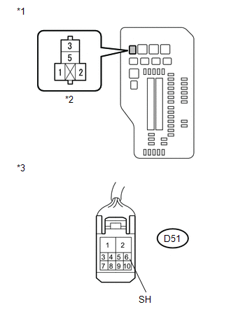
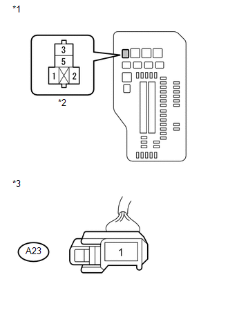
*1 |
Engine Room Relay Block |
|
*2 |
SEC HORN Relay Terminal |
|
*3 |
Front view of wire harness connector (to Main Body ECU (Driver Side Junction Block Assembly)) |
| NG | |
REPAIR OR REPLACE HARNESS OR CONNECTOR |
|
|
6. |
CHECK HARNESS AND CONNECTOR (SEC HORN RELAY POWER SOURCE) |
|
(a) Measure the voltage according to the value(s) in the table below. Standard Voltage:
|
|
| NG | |
REPAIR OR REPLACE HARNESS OR CONNECTOR |
|
|
7. |
CHECK HARNESS AND CONNECTOR (SEC HORN RELAY - SECURITY HORN ASSEMBLY) |
|
(a) Disconnect the A23 security horn assembly connector. |
|
(b) Measure the resistance according to the value(s) in the table below.
Standard Resistance:
|
Tester Connection |
Condition |
Specified Condition |
|---|---|---|
|
Engine room relay block SEC HORN relay terminal 5 - A23-1 |
Always |
Below 1 Ω |
|
Engine room relay block SEC HORN relay terminal 5 - Body ground |
Always |
10 kΩ or higher |
|
*1 |
Engine Room Relay Block |
|
*2 |
SEC HORN Relay Terminal |
|
*3 |
Front view of wire harness connector (to Security Horn Assembly) |
| OK | |
REPLACE MAIN BODY ECU (DRIVER SIDE JUNCTION BLOCK ASSEMBLY) |
| NG | |
REPAIR OR REPLACE HARNESS OR CONNECTOR |
 Horn Circuit
DESCRIPTION
When the theft deterrent system is switched from the armed state to the alarm
sounding state, the main body ECU (driver side junction block assembly) transmits
a signal to cause the h ...
 Security Indicator Light Circuit
DESCRIPTION
Even when the theft deterrent system is in the disarmed state, the security indicator
blinks due to a signal output from the immobiliser system. The security indicator
blinks continuo ...
Other materials about Toyota Venza:
Communication Malfunction between ECUs Connected by LIN (B2785)
DESCRIPTION
This DTC is stored when LIN communication from the certification ECU stops for
a certain amount of time.
DTC No.
DTC Detection Condition
Trouble Area
B2785
Errors in LIN co ...
Display does not Dim when Light Control Switch is Turned ON
PROCEDURE
1.
CHECK IMAGE QUALITY SETTING
(a) Turn the light control switch to the tail or head position.
(b) Check that the daytime screen setting on the display adjustment screen is
set to on.
Result
...
Rear Light Assembly
Components
COMPONENTS
ILLUSTRATION
On-vehicle Inspection
ON-VEHICLE INSPECTION
PROCEDURE
1. INSPECT REAR LIGHT ASSEMBLY
(a) Disconnect the connector from the rear light assembly.
(b) Measu ...

0.1255