Toyota Venza: Seat Position Sensor
Components
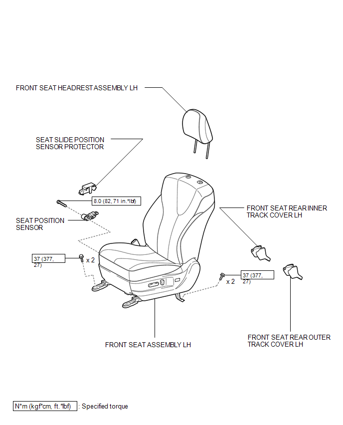
COMPONENTS
ILLUSTRATION
On-vehicle Inspection
ON-VEHICLE INSPECTION
CAUTION / NOTICE / HINT
CAUTION:
Be sure to follow the correct removal and installation procedures of the seat position sensor.
PROCEDURE
1. INSPECT SEAT POSITION SENSOR (VEHICLE NOT INVOLVED IN COLLISION)
(a) Perform a diagnostic system check (See page
.gif) ).
).
2. INSPECT SEAT POSITION SENSOR (VEHICLE INVOLVED IN COLLISION AND AIRBAG HAS NOT DEPLOYED)
(a) Perform a diagnostic system check (See page
).
(b) Visually check for defects with the seat position sensor installed on the vehicle.
(1) The defects are as follows:
- Cracks on the sensor housing
- Dents on the sensor housing
- Chips on the sensor housing
- Cracks or other damage to the connector
OK:
No defects are found.
HINT:
If any of the defects is found, replace the seat position sensor with a new one.
Removal
REMOVAL
PROCEDURE
1. PRECAUTION
CAUTION:
Be sure to read Precaution thoroughly before servicing (See page
.gif) ).
).
2. REMOVE FRONT SEAT ASSEMBLY LH
(See page )
3. REMOVE SEAT POSITION SENSOR
|
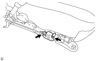
(a) Disconnect the connector. |
|
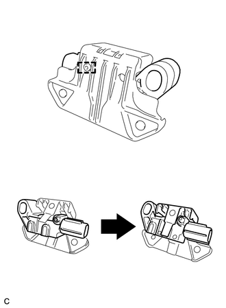
(b) Using a T30 "TORX" socket wrench, remove the "TORX" screw and seat position sensor with the seat slide position sensor protector.
|
(c) Remove the seat position sensor from the seat slide position sensor protector as shown in the illustration. |
|

Installation
INSTALLATION
PROCEDURE
1. INSTALL SEAT POSITION SENSOR
|
(a) Install the seat position sensor to the seat slide position sensor protector with the pin as shown in the illustration. |
|
|
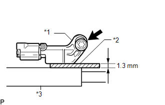
(b) Using a 1.3 mm (0.0512 in.) feeler gauge, temporarily install the seat position sensor. Text in Illustration
NOTICE:
HINT: Be sure that the clearance between the seat position sensor and the seat rail is within 0.6 mm (0.0236 in.) to 2.0 mm (0.0787 in.). |
|
|
(c) Using a T30 "TORX" socket wrench, tighten the "TORX" screw to install the seat position sensor. Torque: 8.0 N·m {82 kgf·cm, 71 in·lbf} |
|
.png)
(d) Make sure that the clearance between the seat position sensor and the seat rail is within 0.6 mm (0.0236 in.) to 2.0 mm (0.0787 in.).
(e) Connect the connector.
(f) Check that there is no looseness in the installation parts of the seat position sensor.
2. INSTALL FRONT SEAT ASSEMBLY LH
(See page .gif) )
)
3. PERFORM DIAGNOSTIC SYSTEM CHECK
(a) Perform a diagnostic system check (See page
).
4. INSPECT SRS WARNING LIGHT
(a) Inspect the SRS warning light (See page
).
 Removal
REMOVAL
CAUTION / NOTICE / HINT
HINT:
Use the same procedure for the RH side and LH side.
The procedure listed below is for the LH side.
PROCEDURE
1. PRECAUTION
CAUTION:
Be su ...

Other materials about Toyota Venza:
Do-it-yourself service precautions
If you perform maintenance yourself, be sure to follow the correct procedure
given in these sections.
CAUTION
The engine compartment contains many mechanisms and fluids that may move suddenly,
become hot, or become electrically energized. To avoid de ...
Reassembly
REASSEMBLY
CAUTION / NOTICE / HINT
HINT:
Use high-temperature grease to lubricate the bearings, gears and return spring
when assembling the starter.
PROCEDURE
1. INSTALL PLANETARY GEAR
(a) Apply grease to the planetary gears and pin parts of ...
Problem Symptoms Table
PROBLEM SYMPTOMS TABLE
HINT:
Use the table below to help determine the cause of problem symptoms.
If multiple suspected areas are listed, the potential causes of the symptoms
are listed in order of probability in the "Suspected Area" ...

0.168