Toyota Venza: Removal
REMOVAL
PROCEDURE
1. REMOVE NO. 1 ENGINE UNDER COVER
2. REMOVE NO. 2 ENGINE UNDER COVER
3. REMOVE WINDSHIELD WIPER MOTOR AND LINK
(a) Remove the windshield wiper motor and link (See page
.gif) ).
).
4. REMOVE OUTER COWL TOP PANEL SUB-ASSEMBLY
5. DRAIN ENGINE COOLANT
6. REMOVE NO. 1 ENGINE COVER SUB-ASSEMBLY
7. REMOVE NO. 1 VACUUM SWITCHING VALVE ASSEMBLY
8. REMOVE AIR CLEANER CAP SUB-ASSEMBLY
9. REMOVE AIR CLEANER FILTER ELEMENT SUB-ASSEMBLY
10. REMOVE AIR CLEANER CASE
11. REMOVE ENGINE COOLANT TEMPERATURE SENSOR
|
(a) Disconnect the engine coolant temperature sensor connector. Text in Illustration
|
|
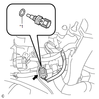
(b) Remove the engine coolant temperature sensor and gasket.
 Inspection
INSPECTION
PROCEDURE
1. INSPECT ENGINE COOLANT TEMPERATURE SENSOR
Text in Illustration
*1
Component without harness connected
(Engine Coolant Temperature Sensor)
...
 Installation
INSTALLATION
PROCEDURE
1. INSTALL ENGINE COOLANT TEMPERATURE SENSOR
(a) Install a new gasket to the sensor.
Text in Illustration
*1
New Gasket
...
Other materials about Toyota Venza:
Sleep Operation Failure of Occupant Classification ECU (B1796)
DESCRIPTION
In sleep mode, the occupant classification ECU reads the condition of each sensor
while the ignition switch is off.
In this mode, if occupant classification ECU detects an internal malfunction,
DTC B1796 is output.
DTC No.
...
Disassembly
DISASSEMBLY
PROCEDURE
1. REMOVE ENGINE COVER JOINT
(a) Remove the 3 joints.
2. REMOVE SPARK PLUG
3. REMOVE CAMSHAFT TIMING OIL CONTROL VALVE ASSEMBLY (for Intake Side)
4. REMOVE CAMSHAFT TIM ...
Diagnosis System
DIAGNOSIS SYSTEM
1. CHECK BATTERY VOLTAGE
Standard voltage:
11 to 14 V
If the voltage is below 11 V, recharge the battery before proceeding to the next
step.
2. CHECK DLC3
(a) The ECU uses ISO 15765-4 for communication. The terminal arrangement of the ...

0.162