Toyota Venza: Removal
REMOVAL
PROCEDURE
1. DISCONNECT CABLE FROM NEGATIVE BATTERY TERMINAL
NOTICE:
When disconnecting the cable, some systems need to be initialized after the cable
is reconnected (See page .gif) ).
).
2. REMOVE NO. 1 ENGINE COVER SUB-ASSEMBLY
3. REMOVE COOL AIR INTAKE DUCT SEAL
4. REMOVE NO. 1 ENGINE UNDER COVER
5. REMOVE NO. 2 ENGINE UNDER COVER
6. DRAIN ENGINE COOLANT
7. REMOVE V-RIBBED BELT
HINT:
See page
8. REMOVE WIRE HARNESS CLAMP BRACKET
9. REMOVE GENERATOR ASSEMBLY
10. DISCONNECT NO. 2 RADIATOR HOSE
11. REMOVE WATER INLET
|
(a) Remove the 2 nuts and water inlet. |
|
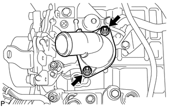
12. REMOVE THERMOSTAT
(a) Remove the thermostat.
(b) Remove the gasket from the thermostat.
 Components
COMPONENTS
ILLUSTRATION
ILLUSTRATION
ILLUSTRATION
...
 Inspection
INSPECTION
PROCEDURE
1. INSPECT THERMOSTAT
HINT:
The valve opening temperature is inscribed on the thermostat.
(a) Immerse the thermostat in water, and then gradually heat the water. ...
Other materials about Toyota Venza:
Reassembly
REASSEMBLY
PROCEDURE
1. REPAIR INSTRUCTION
2. INSTALL REAR DOOR OUTSIDE MOULDING
3. INSTALL REAR DOOR LOWER OUTSIDE STRIPE
4. INSTALL NO. 2 BLACK OUT TAPE
5. INSTALL REAR DOOR OUTSIDE STRIPE
6. INSTALL REAR DOOR UPPER WINDOW FRAME MOULDIN ...
Initialization
INITIALIZATION
NOTICE:
Make sure that the front passenger seat is not occupied before performing the
operation.
HINT:
Perform zero point calibration and sensitivity check if any of the following
conditions occur:
The occupant classification ECU ...
Clock Display Circuit
DESCRIPTION
The accessory meter assembly uses this circuit to communicate with the combination
meter assembly via the direct line. The accessory meter assembly uses this circuit
to receive the drive monitor switch signals from the combination meter assemb ...

0.1331