Toyota Venza: Removal
REMOVAL
PROCEDURE
1. REMOVE INSTRUMENT PANEL REINFORCEMENT ASSEMBLY WITH AIR CONDITIONING UNIT
(See page .gif) )
)
2. REMOVE COOL AIR INTAKE DUCT SEAL
3. REMOVE INLET NO. 2 AIR CLEANER
4. REMOVE AIR CLEANER CAP WITH HOSE
5. REMOVE AIR CLEANER CASE
6. REMOVE FRONT NO. 3 EXHAUST PIPE SUB-ASSEMBLY
7. SEPARATE MANIFOLD STAY
8. REMOVE EXHAUST MANIFOLD SUB-ASSEMBLY RH
9. REMOVE EXHAUST MANIFOLD TO HEAD GASKET
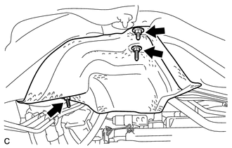
10. REMOVE FRONT NO. 1 FLOOR HEAT INSULATOR
|
(a) Remove the 3 nuts and front No. 1 floor heat insulator. |
|
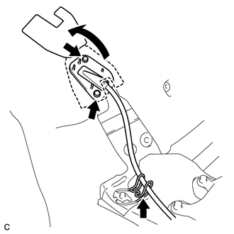
11. REMOVE TRANSMISSION CONTROL CABLE ASSEMBLY
|
(a) Remove the clip and disconnect the transmission control cable assembly from the No. 1 control cable bracket. |
|
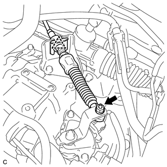
(b) Remove the nut and transmission control cable assembly from the transmission control shaft lever.
|
(c) Disconnect the transmission control cable assembly from the No. 2 transmission control cable bracket. |
|
(d) Turn back the carpet.
(e) Remove the 2 bolts and pull out the transmission control cable assembly from the body.
 Components
COMPONENTS
ILLUSTRATION
ILLUSTRATION
...
 Adjustment
ADJUSTMENT
PROCEDURE
1. INSPECT SHIFT LEVER POSITION
(a) When moving the lever from P to R with the ignition switch ON and the brake
pedal depressed, make sure that the shift lever moves smoothly ...
Other materials about Toyota Venza:
Microphone Circuit between Microphone and Navigation Receiver Assembly
DESCRIPTION
The navigation receiver assembly and inner rear view mirror assembly
(amplifier microphone assembly) are connected to each other using the microphone
connection detection signal lines.
Using this circuit, the navigation receiver ...
Check CAN Bus Lines for Short Circuit
DESCRIPTION
There may be a short circuit in the CAN bus main wire and/or CAN branch wire
when the resistance between terminals 6 (CANH) and 14 (CANL) of the DLC3 is below
54 Ω.
Symptom
Trouble Area
Resistance betwe ...
Precaution
PRECAUTION
NOTICE:
When disconnecting the cable from the negative (-) battery terminal, initialize
the following systems after the cable is reconnected.
System Name
See Procedure
Back Door Closer System
...

0.141