Toyota Venza: Removal
REMOVAL
PROCEDURE
1. DISCONNECT CABLE FROM NEGATIVE BATTERY TERMINAL
NOTICE:
When disconnecting the cable, some systems need to be initialized after the cable
is reconnected (See page .gif) ).
).
2. REMOVE UPPER CONSOLE PANEL SUB-ASSEMBLY (w/o Seat Heater System)
3. REMOVE UPPER CONSOLE PANEL SUB-ASSEMBLY (w/ Seat Heater System)
4. REMOVE NO. 2 CONSOLE BOX CARPET
5. REMOVE CONSOLE BOX ASSEMBLY
6. REMOVE AIR CONDITIONING CONTROL ASSEMBLY
7. REMOVE FRONT DOOR SCUFF PLATE LH
8. REMOVE COWL SIDE TRIM SUB-ASSEMBLY LH
9. REMOVE LOWER NO. 1 INSTRUMENT PANEL FINISH PANEL
10. REMOVE FRONT DOOR SCUFF PLATE RH
11. REMOVE COWL SIDE TRIM SUB-ASSEMBLY RH
12. REMOVE NO. 2 INSTRUMENT PANEL UNDER COVER SUB-ASSEMBLY
13. REMOVE LOWER INSTRUMENT PANEL SUB-ASSEMBLY
14. REMOVE SHIFT LEVER KNOB SUB-ASSEMBLY
15. REMOVE POSITION INDICATOR HOUSING ASSEMBLY
16. REMOVE CONSOLE BOX SUB-ASSEMBLY
17. REMOVE SHIFT LEVER ASSEMBLY
(a) Move the shift lever to N.
|
(b) Disconnect the 2 connectors. |
|
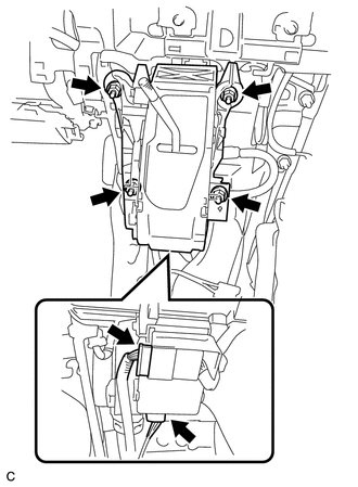
(c) Remove the 4 nuts and shift lever assembly.
|
(d) Disconnect the end of the transmission control cable assembly from the shift lever assembly. |
|
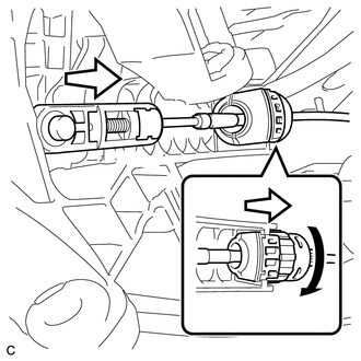
(e) Turn the lock nut counterclockwise. While holding the lock nut, disconnect the transmission control cable from the shift lever retainer.
 Disassembly
DISASSEMBLY
PROCEDURE
1. REMOVE POSITION INDICATOR HOUSING SUB-ASSEMBLY
(a) Remove the shift lever cap from the position indicator housing sub-assembly.
(b) Disengage the 4 claws and re ...
 Inspection
INSPECTION
PROCEDURE
1. INSPECT SHIFT LOCK CONTROL UNIT ASSEMBLY (w/o Smart Key System)
(a) Measure the voltage according to the value(s) in the table below.
Text in Illustration
...
Other materials about Toyota Venza:
Disposal
DISPOSAL
CAUTION / NOTICE / HINT
CAUTION:
Before performing pre-disposal deployment of any SRS component, review and closely
follow all applicable environmental and hazardous material regulations. Pre-disposal
deployment may be considered hazardous mate ...
Front Stabilizer Bar(for 2gr-fe 2wd)
Components
COMPONENTS
ILLUSTRATION
Removal
REMOVAL
PROCEDURE
1. REMOVE FRONT FRAME ASSEMBLY (When Using the Engine Support Bridge)
(See page )
2. REMOVE ENGINE ASSEMBLY WITH TRANSAXLE (When Not Using the Engine Support Bridge)
(See page )
3. ...
Inspection
INSPECTION
PROCEDURE
1. INSPECT INNER REAR VIEW MIRROR ASSEMBLY
(a) Inspect operation of the electrochromic inner mirror.
(1) Connect a positive (+) lead from the battery to terminal 1 and a negative
(-) lead to terminal 2.
(2) Press the AUTO switch.
...

0.1707