Toyota Venza: Removal
REMOVAL
PROCEDURE
1. REMOVE ENGINE ASSEMBLY WITH TRANSAXLE
See page .gif) for 2GR-FE
for 2GR-FE
See page for 1AR-FE
2. REMOVE FRONT NO. 1 STABILIZER BRACKET LH
3. REMOVE FRONT NO. 1 STABILIZER BRACKET RH
HINT:
Perform the same procedure as for the LH side.
4. REMOVE FRONT STABILIZER BAR WITH FRONT STABILIZER LINK ASSEMBLY
5. REMOVE STEERING LINK ASSEMBLY
6. REMOVE FRONT FRAME ASSEMBLY (for 2GR-FE)
7. SEPARATE REAR ENGINE MOUNTING INSULATOR ASSEMBLY (for 1AR-FE)
8. REMOVE FRONT FRAME ASSEMBLY (for 1AR-FE)
9. REMOVE STARTER ASSEMBLY (for 2GR-FE)
10. REMOVE STARTER ASSEMBLY (for 1AR-FE)
11. REMOVE MANIFOLD STAY (for 2GR-FE)
12. REMOVE TRANSFER STIFFENER PLATE RH (for 2GR-FE)
13. REMOVE TRANSFER STIFFENER PLATE RH (for 1AR-FE)
14. SEPARATE WIRE HARNESS (for 2GR-FE)
15. SEPARATE WIRE HARNESS (for 1AR-FE)
16. REMOVE FLEXIBLE HOSE BRACKET SUB-ASSEMBLY (for 2GR-FE)
17. REMOVE AUTOMATIC TRANSAXLE ASSEMBLY (for 2GR-FE)
18. REMOVE AUTOMATIC TRANSAXLE ASSEMBLY (for 1AR-FE)
19. REMOVE TRANSFER ASSEMBLY
|
(a) Remove the 2 bolts and 6 nuts. |
|
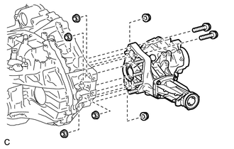
(b) Using a plastic hammer, remove the transfer assembly from the transaxle assembly.
NOTICE:
- Remove the transfer assembly from the transaxle assembly without tilting it.
- During removal, do not hold the transfer assembly by the oil seals on either side of the assembly.
 Components
COMPONENTS
ILLUSTRATION
ILLUSTRATION
ILLUSTRATION
ILLUSTRATION
ILLUSTRATION
ILLUSTRATION
...
 Disassembly
DISASSEMBLY
PROCEDURE
1. REMOVE TRANSFER AND TRANSAXLE SETTING STUD BOLT
(a) Remove the 4 transfer and transaxle setting stud bolts.
2. RE ...
Other materials about Toyota Venza:
Disassembly
DISASSEMBLY
PROCEDURE
1. REMOVE BRAKE MASTER CYLINDER RESERVOIR ASSEMBLY
(a) Mount the brake master cylinder sub-assembly in a vise.
NOTICE:
Place aluminum plates on the vise to prevent damage to the brake master cylinder
sub-assembly.
(b) U ...
Removal
REMOVAL
PROCEDURE
1. REMOVE BACK DOOR PANEL TRIM ASSEMBLY
2. REMOVE REAR WIPER ARM HEAD CAP
(a) Disengage the 4 claws and remove the rear wiper arm head cap as shown
in the illustration.
3. ...
Propeller Shaft System
Problem Symptoms Table
PROBLEM SYMPTOMS TABLE
HINT:
Use the table below to help determine the cause of problem symptoms. If multiple
suspected areas are listed, the potential causes of the symptoms are listed in order
of probability in the "Suspe ...

0.1147