Toyota Venza: Removal
REMOVAL
CAUTION / NOTICE / HINT
HINT:
- Use the same procedure for the LH side and RH side.
- The following procedure listed below is for the LH side.
PROCEDURE
1. REMOVE REAR WHEEL
2. SEPARATE REAR SPEED SENSOR
.gif)
3. REMOVE REAR AXLE SHAFT NUT
|
(a) Using SST and a hammer, release the staked part of the rear axle shaft nut. SST: 09930-00010 NOTICE: Loosen the staked part of the nut completely, otherwise the threads of the drive shaft may be damaged. |
|
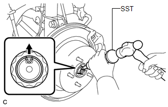
(b) While applying the brakes, remove the rear axle shaft nut.
4. SEPARATE REAR DISC BRAKE CALIPER ASSEMBLY
5. REMOVE REAR DISC
6. REMOVE REAR AXLE HUB AND BEARING ASSEMBLY
7. SEPARATE NO. 3 PARKING BRAKE CABLE ASSEMBLY
8. REMOVE REAR STRUT ROD ASSEMBLY
9. REMOVE REAR AXLE CARRIER SUB-ASSEMBLY
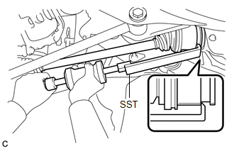
10. REMOVE REAR DRIVE SHAFT ASSEMBLY
|
(a) Using SST, remove the rear drive shaft assembly as shown in the illustration. SST: 09520-01010 SST: 09520-24010 09520-32040 NOTICE: Remove the rear drive shaft assembly while keeping it level. |
|
 Components
COMPONENTS
ILLUSTRATION
ILLUSTRATION
...
 Disassembly
DISASSEMBLY
PROCEDURE
1. REMOVE REAR DRIVE SHAFT SNAP RING
(a) Using a screwdriver, remove the rear drive shaft snap ring.
2. REMOVE NO. 2 ...
Other materials about Toyota Venza:
Speed Sensor(when Using The Engine Support Bridge)
Components
COMPONENTS
ILLUSTRATION
Removal
REMOVAL
PROCEDURE
1. REMOVE TRANSMISSION VALVE BODY ASSEMBLY
See page
2. REMOVE SPEED SENSOR
(a) Disconnect the speed sensor connector.
(b) Remove the 2 bolts and speed sensor from the tra ...
Main Body ECU Communication Stop Mode
DESCRIPTION
Detection Item
Symptom
Trouble Area
Main Body ECU Communication Stop Mode
"Main Body" is not displayed on "CAN Bus Check" screen of the
Techstream.
...
On-vehicle Inspection
ON-VEHICLE INSPECTION
PROCEDURE
1. INSPECT SHIFT LOCK CONTROL UNIT ASSEMBLY
(a) Inspect the shift lock operation.
(1) Move the shift lever to P.
(2) Turn the ignition switch off.
(3) Check that the shift lever cannot be moved from P to any other position ...

0.1172