Toyota Venza: Removal
REMOVAL
PROCEDURE
1. REMOVE TAIL EXHAUST PIPE ASSEMBLY (for 1AR-FE)
.gif)
2. REMOVE TAIL EXHAUST PIPE ASSEMBLY (for 2GR-FE)
3. REMOVE CENTER EXHAUST PIPE ASSEMBLY (for 1AR-FE)
4. REMOVE CENTER EXHAUST PIPE ASSEMBLY (for 2GR-FE)
5. REMOVE PROPELLER WITH CENTER BEARING SHAFT ASSEMBLY
(a) Depress the brake pedal and hold it.
|
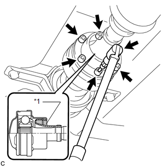
(b) Using a hexagon wrench (6 mm), loosen the cross groove joint set bolts 1/2 turn. NOTICE:
|
|
|
(c) Place matchmarks on the rear propeller shaft and electromagnetic control coupling assembly. Text in Illustration
|
|
|
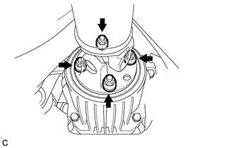
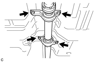
(d) Remove the 4 nuts and 4 washers. |
|
|
(e) Using a brass bar and a hammer, separate the propeller with center bearing shaft assembly. |
|
|
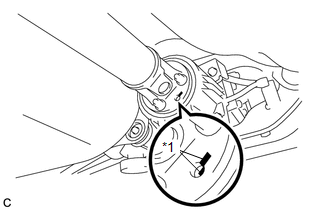
(f) Remove the 4 bolts, 2 No. 1 center support bearing washers and 2 No. 2 center support bearing washers. NOTICE: When removing the bolts and washers, do not apply excessive force to the universal joint. |
|
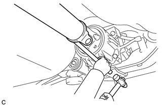
(g) Pull out the propeller with center bearing shaft assembly from the transfer.
NOTICE:
- When removing the propeller shaft, do not apply excessive force to the universal joint.
- During and after the removal of the propeller shaft, keep the universal joint angle straight (within 15 degrees).
- Be careful not to damage the oil seal.
|
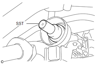
(h) Insert SST into the transfer to prevent oil leaks. SST: 09325-20010 NOTICE: Be careful not to damage the oil seal. |
|
 Components
COMPONENTS
ILLUSTRATION
ILLUSTRATION
ILLUSTRATION
ILLUSTRATION
...
 Disassembly
DISASSEMBLY
PROCEDURE
1. REMOVE PROPELLER SHAFT
(a) Place matchmarks on both flanges.
Text in Illustration
*1
Matchmark
...
Other materials about Toyota Venza:
Removal
REMOVAL
CAUTION / NOTICE / HINT
NOTICE:
When disconnecting the steering intermediate shaft assembly and pinion shaft
of the steering gear assembly, be sure to place matchmarks before servicing.
PROCEDURE
1. PLACE FRONT WHEELS FACING STRAIGHT AHEAD
2. S ...
USB Audio System Recognition/Play Error
DESCRIPTION
When a USB device or "iPod" is connected to the USB jack of the No. 1 stereo
jack adapter assembly, it must have playable files. The device must also communicate
with and be recognized by the navigation receiver assembly. This diagno ...
Power Seat does not Return to Memorized Position
DESCRIPTION
When either the M1 or M2 switch is pressed, the outer mirror control ECU assembly
LH sends a switch signal to the main body ECU (driver side junction block assembly)
via CAN communication. Then, the main body ECU (driver side junction block as ...

0.1266