Toyota Venza: Removal
REMOVAL
CAUTION / NOTICE / HINT
HINT:
- Use the same procedure for the RH side and LH side.
- The procedure listed below is for the LH side.
PROCEDURE
1. REMOVE REAR WHEEL
2. SEPARATE REAR DISC BRAKE CALIPER ASSEMBLY
.gif)
3. REMOVE REAR DISC
4. SEPARATE REAR SPEED SENSOR WIRE
5. SEPARATE NO. 3 PARKING BRAKE CABLE ASSEMBLY
6. REMOVE REAR AXLE HUB AND BEARING ASSEMBLY
7. REMOVE REAR STRUT ROD ASSEMBLY
8. REMOVE REAR AXLE CARRIER SUB-ASSEMBLY
|
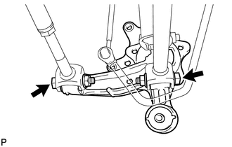
(a) Loosen the 2 bolts. NOTICE: Since stopper nuts are used, loosen the bolts. |
|
|
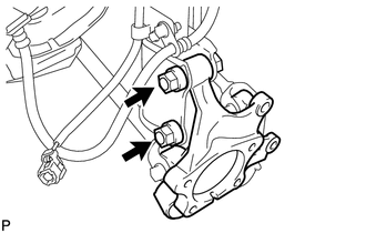
(b) Remove the 2 bolts and 2 nuts, and separate the rear axle carrier sub-assembly from the rear shock absorber with coil spring. NOTICE: When removing the nuts, keep the bolts from rotating. |
|
|
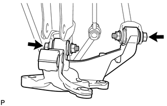
(c) Remove the 2 bolts, 2 nuts and rear axle carrier sub-assembly. |
|
 Components
COMPONENTS
ILLUSTRATION
...
 Installation
INSTALLATION
CAUTION / NOTICE / HINT
HINT:
Use the same procedure for the RH side and LH side.
The procedure listed below is for the LH side.
PROCEDURE
1. INSTALL REAR AXLE CARR ...
Other materials about Toyota Venza:
If the engine will not start
If the engine still does not start after following the correct starting procedure
(, 175) or releasing the steering lock (, 176), confirm the following points.
- The engine will not start even if you are carrying the correct key.
One of the followi ...
Brake
General Maintenance
GENERAL MAINTENANCE
PROCEDURE
1. INSPECT BRAKE LINE PIPES AND HOSES
HINT:
Work in a well-lighted area. Turn the front wheels fully to the right or left
before beginning the inspection.
(a) Using a mirror, check the entire circum ...
Slip Indicator Light Remains ON
DESCRIPTION
The skid control ECU is connected to the combination meter via CAN communication.
The slip indicator light blinks during VSC and/or TRAC operation.
When the system fails, the slip indicator light comes on to warn the driver (See
page ).
WIRI ...

0.1653