Toyota Venza: Removal
REMOVAL
PROCEDURE
1. REMOVE PARKING BRAKE PEDAL ASSEMBLY
HINT:
Refer to the instructions for Removal of the parking brake pedal assembly (See
page .gif) ).
).
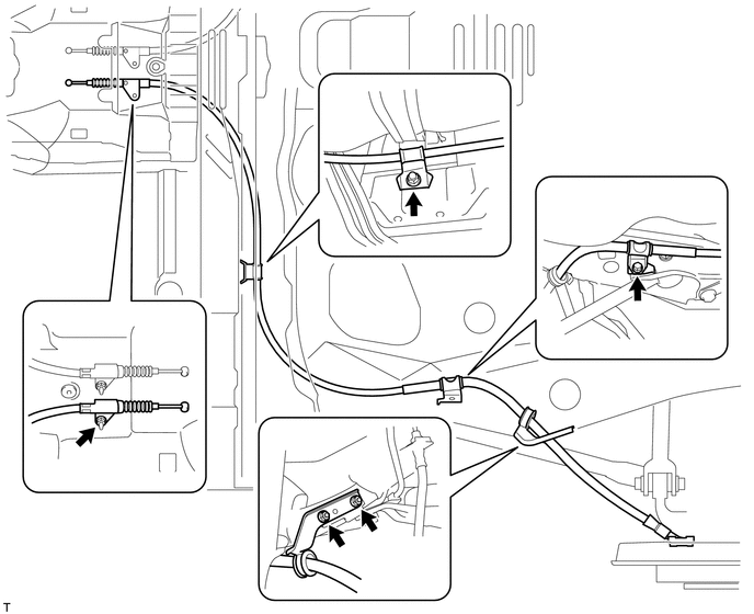
2. REMOVE NO. 1 PARKING BRAKE CABLE ASSEMBLY
|
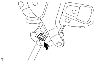
(a) Remove the clip. |
|
|
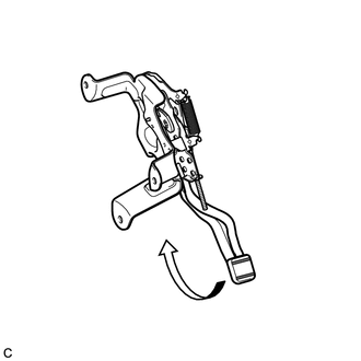
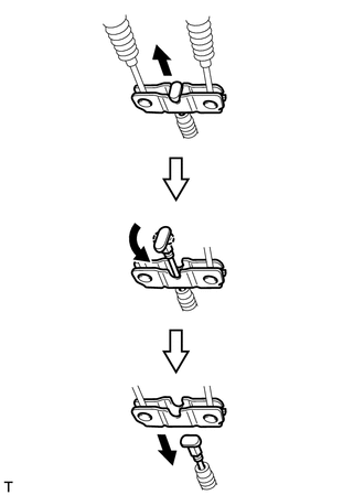
(b) Depress the parking brake pedal. |
|
|
(c) Pull up the parking brake pedal claw and remove the No. 1 parking brake cable assembly from the parking brake pedal assembly. |
|
3. REMOVE REAR WHEEL
4. REMOVE NO. 4 PARKING BRAKE CABLE ASSEMBLY
|
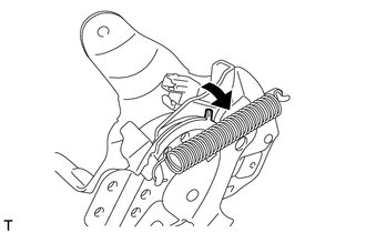
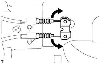
(a) Slide the rubber boot as shown in the illustration. |
|
|
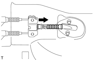
(b) Separate the No. 4 parking brake cable assembly from the parking brake equalizer as shown in the illustration. |
|
|
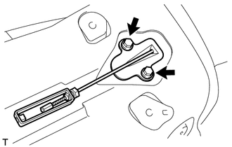
(c) Remove the 2 bolts and No. 4 parking brake cable assembly. |
|
5. REMOVE PARKING BRAKE EQUALIZER
|
(a) Move the No. 2 parking brake cable assembly and No. 3 parking brake cable assembly as shown in the illustration to remove the parking brake equalizer. |
|
6. REMOVE NO. 2 PARKING BRAKE SHOE ASSEMBLY WITH PARKING BRAKE SHOE LEVER
HINT:
Refer to the instructions for Removal of the No. 2 parking brake shoe assembly
with parking brake shoe lever (See page ).
7. REMOVE NO. 3 PARKING BRAKE CABLE ASSEMBLY
|
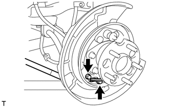
(a) Remove the 2 bolts and separate the No. 3 parking brake cable assembly from the backing plate. |
|
(b) Remove the bolt, 4 nuts and the No. 3 parking brake cable assembly.
8. REMOVE NO. 2 PARKING BRAKE CABLE ASSEMBLY
HINT:
Use the same procedure as for the No. 3 parking brake cable assembly.
 Components
COMPONENTS
ILLUSTRATION
ILLUSTRATION
ILLUSTRATION
...
 Installation
INSTALLATION
PROCEDURE
1. INSTALL NO. 3 PARKING BRAKE CABLE ASSEMBLY
(a) Install the No. 3 parking brake cable assembly with the bolt and 4 nuts.
Torque:
Nut (A) :
5.4 N·m {55 kgf·cm, 48 i ...
Other materials about Toyota Venza:
Throttle / Pedal Position Sensor / Switch "A" Circuit Malfunction (P0120-P0123,P0220,P0222,P0223,P2135)
DESCRIPTION
HINT:
These DTCs relate to the throttle position sensor.
The throttle position sensor is mounted on the throttle body, and detects the
opening angle of the throttle valve. This sensor is a non-contact type sensor. It
uses hall-effect element ...
Internal Control Module Monitoring Processor Performance (P060A)
MONITOR DESCRIPTION
The main CPU and sub CPU of the ECM perform data communication between each other.
The main CPU monitors the communications and WDC pulses from the sub CPU. When the
signal malfunctions below are detected, the DTC is output.
...
Data List / Active Test
DATA LIST / ACTIVE TEST
1. DATA LIST
HINT:
Using the Techstream to read the Data List allows the values or states of switches,
sensors, actuators and other items to be read without removing any parts. This non-intrusive
inspection can be very useful bec ...

0.144