Toyota Venza: Removal
REMOVAL
CAUTION / NOTICE / HINT
NOTICE:
Release the vacuum from the booster by depressing the brake pedal several times. Then remove the brake master cylinder from the brake booster.
PROCEDURE
1. REMOVE FRONT WIPER ARM HEAD CAP
2. REMOVE FRONT WIPER ARM AND BLADE ASSEMBLY LH
.gif)
3. REMOVE FRONT WIPER ARM AND BLADE ASSEMBLY RH
4. REMOVE FRONT FENDER TO COWL SIDE SEAL LH
5. REMOVE FRONT FENDER TO COWL SIDE SEAL RH
6. REMOVE COWL TOP VENTILATOR LOUVER SUB-ASSEMBLY
7. REMOVE WINDSHIELD WIPER MOTOR AND LINK ASSEMBLY
8. REMOVE OUTER COWL TOP PANEL
9. REMOVE AIR CLEANER CAP SUB-ASSEMBLY (for 1AR-FE)
10. REMOVE AIR CLEANER CAP SUB-ASSEMBLY (for 2GR-FE)
11. REMOVE AIR CLEANER FILTER ELEMENT SUB-ASSEMBLY
12. REMOVE AIR CLEANER CASE (for 1AR-FE)
13. REMOVE AIR CLEANER CASE (for 2GR-FE)
14. REMOVE SECURITY HORN ASSEMBLY (w/ Security Horn)
15. REMOVE BRAKE MASTER CYLINDER SUB-ASSEMBLY
16. SEPARATE NO. 1 VACUUM HOSE CONNECTOR (for 1AR-FE)
|
(a) Slide the clip and disconnect the vacuum hose from the brake booster assembly. |
|
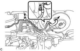
(b) Remove the 2 nuts and separate the No. 1 vacuum hose connector.
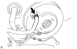
17. DISCONNECT VACUUM HOSE (for 2GR-FE)
|
(a) Slide the clip and disconnect the vacuum hose from the brake booster assembly. |
|
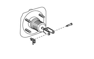
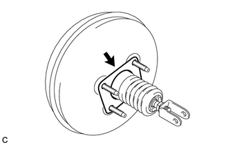
18. REMOVE PUSH ROD PIN
|
(a) Remove the clip and push rod pin. |
|
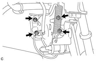
19. REMOVE BRAKE BOOSTER ASSEMBLY
|
(a) Remove the 4 nuts and brake booster assembly from the body. NOTICE: Do not damage the brake lines. |
|
20. REMOVE BRAKE BOOSTER GASKET
|
(a) Remove the brake booster gasket from the brake booster assembly. |
|
21. REMOVE BRAKE MASTER CYLINDER PUSH ROD CLEVIS
(a) Loosen the lock nut, and remove the brake master cylinder push rod clevis and lock nut.
22. REMOVE BRAKE VACUUM CHECK VALVE ASSEMBLY
(a) Remove the brake vacuum check valve assembly from the brake booster assembly.
23. REMOVE CHECK VALVE GROMMET
(a) Remove the check valve grommet from the brake booster assembly.
 On-vehicle Inspection
ON-VEHICLE INSPECTION
PROCEDURE
1. INSPECT BRAKE BOOSTER ASSEMBLY
(a) Airtightness check
(1) Start the engine and stop it after 1 or 2 minutes. Slowly depress
the brake pedal seve ...
 Inspection
INSPECTION
PROCEDURE
1. INSPECT BRAKE VACUUM CHECK VALVE ASSEMBLY
(a) Check that there is ventilation from the booster to the engine, and
no ventilation from the engine to the booste ...
Other materials about Toyota Venza:
Inspection
INSPECTION
PROCEDURE
1. INSPECT STEERING PAD SWITCH ASSEMBLY
(a) Measure the resistance according to the value(s) in the table below.
Standard Resistance:
Tester Connection
Condition
Specified Condition
...
Freeze Frame Data
FREEZE FRAME DATA
1. FREEZE FRAME DATA
NOTICE:
Freeze frame data values will vary depending on the measurement conditions,
surroundings, or vehicle conditions. For this reason, there may be a problem
even when the values are within specifica ...
Lost Communication with Gateway Module (MS Bus) (U1002)
DESCRIPTION
The main body ECU will store this DTC when no signals can be received
from the ECUs that have been memorized as those that are connected to the
CAN MS bus.
When the main body ECU receives a response signal from the ECUs connecte ...

0.1609