Toyota Venza: Removal
REMOVAL
PROCEDURE
1. REMOVE REAR SEAT HEADREST ASSEMBLY
|
(a) Press the headrest support button and pull up the rear seat headrest assembly as shown in the illustration. |
|

2. REMOVE REAR SEAT CENTER HEADREST ASSEMBLY
|
(a) Press the headrest support button and pull up the rear seat center headrest assembly as shown in the illustration. |
|

3. REMOVE REAR SEAT INNER TRACK BRACKET COVER
|
(a) Disengage the 3 claws and guide, and remove the rear seat inner track bracket cover as shown in the illustration. |
|

4. REMOVE REAR SEAT OUTER TRACK BRACKET COVER
|
(a) Disengage the 3 claws and guide, and remove the rear seat outer track bracket cover as shown in the illustration. |
|

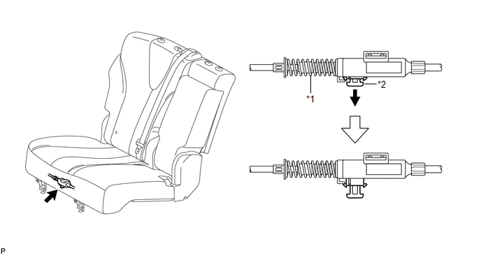
5. DISCONNECT REAR SEAT RECLINING CONTROL CABLE SUB-ASSEMBLY
(a) Pull down the adjuster's lock piece to release the lock as shown in the illustration.
 Text in Illustration
|
*1 |
Adjuster Spring |
*2 |
Lock Piece |
|
(b) Using a screwdriver wrapped with protective tape, disengage the 2 claws as shown in the illustration. Text in Illustration
|
|

(c) Lift up the seat track adjusting handle to the uppermost position and hold the handle in this position as shown in the illustration.
 Text in Illustration
|
*1 |
Protective Tape |
*2 |
Seat Track Adjusting Handle |
(d) Using a screwdriver wrapped with protective tape, disconnect the rear seat reclining control cable sub-assembly as shown in the illustration.
 Text in Illustration
|
*1 |
Protective Tape |
6. REMOVE REAR SEAT ASSEMBLY RH
|
(a) Remove the 3 bolts on the rear side of the seat. |
|

|
(b) Remove the 2 bolts on the front side of the rear seat assembly RH. |
|

(c) Remove the rear seat assembly RH.
NOTICE:
Be careful not to damage the vehicle body.
 Components
COMPONENTS
ILLUSTRATION
ILLUSTRATION
ILLUSTRATION
ILLUSTRATION
ILLUSTRATION
...
 Disassembly
DISASSEMBLY
PROCEDURE
1. REMOVE SEAT ADJUSTER COVER CAP RH
(a) Using a screwdriver wrapped with protective tape, disengage the 3
claws and remove the seat adjuster cover cap RH.
T ...
Other materials about Toyota Venza:
Stop Light Switch
Components
COMPONENTS
ILLUSTRATION
Removal
REMOVAL
PROCEDURE
1. REMOVE STOP LIGHT SWITCH ASSEMBLY
(a) Disconnect the connector.
(b) Turn the stop light switch assembly countercl ...
Installation
INSTALLATION
PROCEDURE
1. INSTALL INSTRUMENT PANEL STAY
(a) Engage the 3 claws to install the 3 instrument panel stays.
2. INSTALL INSTRUMENT PANEL CLIP
(a) Engage the 2 claws to install ...
Transmitter ID1 Operation Stop (C2111/11-C2114/14)
DESCRIPTION
The tire pressure warning valve and transmitter installed in each tire and wheel
assembly measures the tire pressures. The measured values are transmitted as radio
waves to the tire pressure warning antenna and receiver on the body and then se ...

0.1415