Toyota Venza: Removal
REMOVAL
PROCEDURE
1. REMOVE FRONT SEAT HEADREST ASSEMBLY
2. REMOVE FRONT SEAT REAR OUTER TRACK COVER
.gif)
3. REMOVE FRONT SEAT REAR INNER TRACK COVER
4. REMOVE FRONT SEAT ASSEMBLY
5. REMOVE SLIDE AND VERTICAL POWER SEAT SWITCH KNOB
6. REMOVE RECLINING POWER SEAT SWITCH KNOB
7. REMOVE FRONT SEAT CUSHION SHIELD ASSEMBLY
8. REMOVE POWER SEAT SWITCH
9. REMOVE FRONT SEAT INNER BELT ASSEMBLY
10. REMOVE FRONT INNER SEAT CUSHION SHIELD
11. REMOVE SEPARATE TYPE FRONT SEAT CUSHION COVER WITH PAD
12. REMOVE FRONT SEATBACK BOARD SUB-ASSEMBLY
13. REMOVE SEPARATE TYPE FRONT SEATBACK COVER WITH PAD
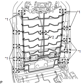
14. REMOVE LUMBAR SUPPORT ADJUSTER ASSEMBLY
|
(a) Disengage the 8 guides and clamp and remove the front seatback spring sub-assembly. Text in Illustration
|
|
(b) Disconnect the connector.
|
(c) Disengage the 2 screws and guide, and remove the lumbar support adjuster assembly. |
|
.png)
|
(d) Remove the bush. |
|
.png)
 Inspection
INSPECTION
PROCEDURE
1. INSPECT LUMBAR SUPPORT ADJUSTER ASSEMBLY
(a) Check operation of the lumbar support adjuster.
(1) Check if the lumbar support adjuster moves smoothly when the battery is c ...
 Installation
INSTALLATION
PROCEDURE
1. INSTALL LUMBAR SUPPORT ADJUSTER ASSEMBLY
(a) Install the bush.
(b) Install the lumbar support adjuste ...
Other materials about Toyota Venza:
Removal
REMOVAL
PROCEDURE
1. REMOVE FRONT SEAT ASSEMBLY LH
(See page )
2. REMOVE FRONT DOOR SCUFF PLATE LH
3. REMOVE COWL SIDE TRIM SUB-ASSEMBLY LH
4. REMOVE FRONT DOOR OPENING TRIM WEATHERSTRIP LH
5. REMOVE REAR DOOR SCUFF PLATE LH
6. REMOVE REAR ...
Knock Sensor 1 Circuit Low Input (Bank 1 or Single Sensor) (P0327,P0328)
DESCRIPTION
Flat-type knock sensors (non-resonant type) have structures that can detect vibrations
between approximately 5 and 15 kHz.
Knock sensors are fitted onto the engine block to detect engine knocking.
The knock sensor contains a piezoelectric elem ...
Control Module Performance (P0607)
MONITOR DESCRIPTION
The ECM continuously monitors its internal processors (CPUs) and heated oxygen
sensor transistors. This self-check ensures that the ECM is functioning properly.
DTC No.
DTC Detection Condition
Trouble Ar ...

0.1662