Toyota Venza: Removal
REMOVAL
PROCEDURE
1. PRECAUTION
CAUTION:
- Be sure to read Precaution thoroughly before servicing (See page
.gif) ).
). - If the front seat side airbag assembly was deployed, replace the front seat side airbag assembly, front seat frame assembly with adjuster, separate type front seatback cover and separate type front seatback pad with the necessary parts in accordance with the extent of the collision damage.
2. REMOVE FRONT SEAT HEADREST ASSEMBLY
3. REMOVE FRONT SEAT REAR OUTER TRACK COVER
(a) Operate the slide and vertical power seat switch knob and move the front seat assembly to the foremost position.
|
(b) Disengage the 2 claws and remove the front seat rear outer track cover. |
|

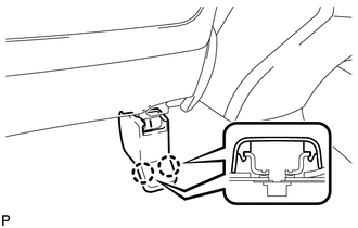
4. REMOVE FRONT SEAT REAR INNER TRACK COVER
|
(a) Disengage the 2 claws and remove the front seat rear inner track cover. |
|
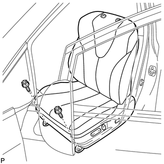
5. REMOVE FRONT SEAT ASSEMBLY
|
(a) Remove the 2 bolts on the rear side of the front seat assembly. |
|

(b) Operate the slide and vertical power seat switch knob and move the front seat assembly to the rearmost position.
|
(c) Remove the 2 bolts on the front side of the front seat assembly. |
|
(d) Operate the slide and vertical power seat switch knob and move the front seat assembly to the center position. Also, operate the reclining power seat switch knob and move the front seatback assembly to the upright position.
(e) Disconnect the cable from the negative (-) battery terminal.
CAUTION:
Wait at least 90 seconds after disconnecting the cable from the negative (-) battery terminal to disable the SRS system.
NOTICE:
When disconnecting the cable, some systems need to be initialized after the cable
is reconnected (See page ).
(f) Disconnect each connector under the front seat assembly.
(g) Remove the front seat assembly.
NOTICE:
Be careful not to damage the vehicle body.
 Components
COMPONENTS
ILLUSTRATION
ILLUSTRATION
ILLUSTRATION
ILLUSTRATION
ILLUSTRATION
ILLUSTRATION
...
 Disassembly
DISASSEMBLY
PROCEDURE
1. REMOVE SEAT ADJUSTER COVER CAP
(a) Remove the seat adjuster cover cap.
HINT:
Use the same procedure for the RH side and LH side.
...
Other materials about Toyota Venza:
Terminals Of Ecu
TERMINALS OF ECU
1. CHECK MAIN BODY ECU (DRIVER SIDE JUNCTION BLOCK ASSEMBLY)
(a) Disconnect the 2A and 2F main body ECU (driver side junction block assembly)
connectors.
(b) Measure the voltage and resistance according to the value(s) in the table
be ...
System Diagram
SYSTEM DIAGRAM
Communication Table
Transmitting ECU
Receiving ECU
Signal
Communication Method
Air Conditioning Control Assembly
Air Conditioning Amplifier Assembly
Rear windo ...
Touch Sensor Circuit
DESCRIPTION
When the power back door ECU receives a jam signal from the touch sensor while
the power back door is operating, the ECU reverses the back door operation and opens
the door.
WIRING DIAGRAM
PROCEDURE
1.
READ VALUE US ...

0.1395