Toyota Venza: Removal
REMOVAL
PROCEDURE
1. REMOVE UPPER CONSOLE PANEL SUB-ASSEMBLY (w/o Seat Heater System)
.gif)
2. REMOVE UPPER CONSOLE PANEL SUB-ASSEMBLY (w/ Seat Heater System)
3. REMOVE NO. 2 CONSOLE BOX CARPET
4. REMOVE CONSOLE BOX ASSEMBLY
5. REMOVE AIR CONDITIONING CONTROL ASSEMBLY
6. REMOVE FRONT DOOR SCUFF PLATE LH
7. REMOVE COWL SIDE TRIM SUB-ASSEMBLY LH
8. REMOVE LOWER NO. 1 INSTRUMENT PANEL FINISH PANEL
9. REMOVE FRONT DOOR SCUFF PLATE RH
HINT:
Use the same procedure for the RH side and LH side (See page
).
10. REMOVE COWL SIDE TRIM SUB-ASSEMBLY RH
HINT:
Use the same procedure for the RH side and LH side (See page
).
11. REMOVE NO. 2 INSTRUMENT PANEL UNDER COVER SUB-ASSEMBLY
12. REMOVE LOWER INSTRUMENT PANEL SUB-ASSEMBLY
13. REMOVE SHIFT LEVER KNOB SUB-ASSEMBLY
14. REMOVE POSITION INDICATOR HOUSING ASSEMBLY
15. REMOVE CONSOLE BOX SUB-ASSEMBLY
16. REMOVE NO. 2 INSTRUMENT PANEL SPEAKER PANEL SUB-ASSEMBLY
17. REMOVE RADIO AND DISPLAY RECEIVER ASSEMBLY WITH BRACKET (for Radio and Display Type)
18. REMOVE NAVIGATION RECEIVER ASSEMBLY WITH BRACKET (for Navigation Receiver Type)
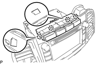
19. REMOVE DRIVE MONITOR SWITCH
|
(a) Disengage the 4 claws and remove the drive monitor switch. |
|
 Inspection
INSPECTION
PROCEDURE
1. INSPECT DRIVE MONITOR SWITCH
(a) Measure the resistance according to the value(s) in the table below.
Standard Resistance:
Tester Connection
Condi ...
 Installation
INSTALLATION
PROCEDURE
1. INSTALL DRIVE MONITOR SWITCH
(a) Engage the 4 claws to install the drive monitor switch.
2. INSTALL RADIO AND DISPLAY RECEIVER ASSEMBLY WITH BRACKET (for Radio and Displa ...
Other materials about Toyota Venza:
Pressure Control Solenoid "D" Performance (Shift Solenoid Valve SLT) (P2714)
SYSTEM DESCRIPTION
The linear solenoid valve (SLT) controls the transmission line pressure for smooth
transmission operation based on signals from the throttle position sensor and the
vehicle speed sensor. The TCM adjusts the current to SLT solenoid valve ...
Panel Switches do not Function
PROCEDURE
1.
CHECK PANEL SWITCH
(a) Check for foreign matter around the switches that might prevent operation.
OK:
No foreign matter is found.
NG
REMOVE ANY FOREIGN MATTER FOUND
...
Rear Speed Sensor RH Circuit (C0210/33,C0215/34,C1273/73,C1274/74,C1332/38,C1333/39)
DESCRIPTION
The speed sensor detects the wheel speed and sends the appropriate signals to
the skid control ECU. These signals are used for the ABS control system.
Speed sensor rotors have rows of alternating N and S magnetic poles (for 2WD)
or 48 serrati ...

0.1219