Toyota Venza: Removal
REMOVAL
PROCEDURE
1. REMOVE AIR CONDITIONING UNIT ASSEMBLY
(See page .gif) )
)
2. REMOVE NO. 1 FINISH PANEL MOUNTING BRACKET
3. REMOVE NO. 2 FINISH PANEL MOUNTING BRACKET
4. REMOVE NO. 3 AIR DUCT SUB-ASSEMBLY
5. REMOVE NO. 2 AIR DUCT SUB-ASSEMBLY
6. REMOVE AIR CONDITIONING HARNESS ASSEMBLY
7. REMOVE COOLER EXPANSION VALVE
8. REMOVE BLOWER ASSEMBLY WITH COOLER EVAPORATOR SUB-ASSEMBLY
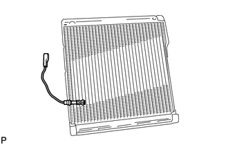
9. REMOVE COOLER EVAPORATOR SUB-ASSEMBLY
10. REMOVE NO. 1 COOLER THERMISTOR
|
(a) Remove the No. 1 cooler thermistor. |
|
 Components
COMPONENTS
ILLUSTRATION
ILLUSTRATION
...
 Inspection
INSPECTION
PROCEDURE
1. INSPECT EVAPORATOR TEMPERATURE SENSOR
(a) Measure the resistance according to the value(s) in the table below.
Standard Resistance:
Tester Connection
...
Other materials about Toyota Venza:
Oxygen (A/F) Sensor Heater Control Circuit Low (Bank 1 Sensor 1) (P0031,P0032,P101D)
DESCRIPTION
Refer to DTC P2195 (See page ).
HINT:
When any of these DTCs is stored, the ECM enters fail-safe mode. The
ECM turns off the air fuel ratio sensor heater in fail-safe mode. Fail-safe
mode continues until the ignition switch is t ...
Evaporative Emission Control System Incorrect Purge Flow (P0441)
DTC SUMMARY
DTC No.
Monitoring Item
Malfunction Detection Condition
Trouble Area
Detection Timing
Detection Logic
P0441
Purge VSV (Vacuum Switching Valve) stuck open ...
Removal
REMOVAL
CAUTION / NOTICE / HINT
HINT:
Use the same procedure for the RH side and LH side.
The procedure listed below is for the LH side.
PROCEDURE
1. REMOVE REAR WHEEL
2. SEPARATE REAR SPEED SENSOR
(a) Remove the bolt and se ...

0.1731