Toyota Venza: Removal
REMOVAL
PROCEDURE
1. ALIGN FRONT WHEELS FACING STRAIGHT AHEAD
2. DISCONNECT CABLE FROM NEGATIVE BATTERY TERMINAL
CAUTION:
Wait at least 90 seconds after disconnecting the cable from the negative (-) battery terminal to disable the SRS system.
NOTICE:
When disconnecting the cable, some systems need to be initialized after the cable
is reconnected (See page .gif) ).
).
3. REMOVE LOWER NO. 3 STEERING WHEEL COVER
4. REMOVE LOWER NO. 2 STEERING WHEEL COVER
5. REMOVE STEERING PAD
6. REMOVE STEERING WHEEL ASSEMBLY
7. REMOVE LOWER STEERING COLUMN COVER
8. REMOVE UPPER STEERING COLUMN COVER
9. REMOVE TURN SIGNAL SWITCH ASSEMBLY WITH SPIRAL CABLE SUB-ASSEMBLY
10. REMOVE UNLOCK WARNING SWITCH
|
(a) Disconnect the connector. |
|
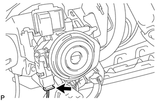
(b) Insert the key into the ignition key cylinder.
|
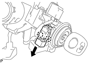
(c) Disengage the 2 claws and remove the unlock warning switch from the steering column upper bracket. |
|
 Inspection
INSPECTION
PROCEDURE
1. INSPECT UNLOCK WARNING SWITCH ASSEMBLY
(a) Measure the resistance according to the value(s) in the table below.
Standard Resistance:
Tester Connection
...
 Installation
INSTALLATION
PROCEDURE
1. INSTALL UNLOCK WARNING SWITCH
(a) Engage the 2 claws and install the unlock warning switch to the steering
column upper bracket.
...
Other materials about Toyota Venza:
ECM Power Source Circuit
DESCRIPTION
When the ignition switch is turned to ON, the battery voltage is applied to IGSW
of the ECM. The output signal from the MREL terminal of the ECM causes a current
to flow to the coil, closing the contact of the engine room junction block assemb ...
Inspection
INSPECTION
PROCEDURE
1. INSPECT LUMBAR SUPPORT ADJUSTER ASSEMBLY
(a) Check operation of the lumbar support adjuster.
(1) Check if the lumbar support adjuster moves smoothly when the battery is connected
to the lumbar support adjuster motor connector te ...
Removal
REMOVAL
CAUTION / NOTICE / HINT
HINT:
Use the same procedure for the RH side and LH side.
The procedure listed below is for the LH side.
PROCEDURE
1. REMOVE REAR WHEEL
2. SEPARATE REAR FLEXIBLE HOSE
3. SEPARATE REAR DISC BRAKE CALIP ...

0.1361