Toyota Venza: Removal
REMOVAL
PROCEDURE
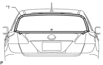
1. REMOVE UPPER BACK WINDOW PANEL TRIM
.gif)
2. REMOVE BACK DOOR PANEL TRIM ASSEMBLY
3. DISCONNECT POWER BACK DOOR ROD (w/ Power Back Door)
4. REMOVE BACK DOOR TRIM COVER LH (w/o Power Back Door)
5. REMOVE BACK DOOR TRIM COVER LH (w/ Power Back Door)
6. REMOVE BACK DOOR TRIM COVER RH
7. REMOVE REAR SPOILER ASSEMBLY
8. REMOVE REAR WIPER ARM HEAD CAP
9. REMOVE REAR WIPER ARM AND BLADE ASSEMBLY
10. REMOVE REAR WIPER MOTOR GROMMET
11. REMOVE REAR WIPER MOTOR AND BRACKET ASSEMBLY
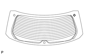
12. REMOVE BACK DOOR GLASS
|
(a) Disconnect the 3 connectors. |
|
.png)
|
(b) Apply protective tape to the outer surface of the vehicle body to prevent scratches. Text in Illustration
NOTICE: When separating the back door glass from the vehicle, be careful not to damage the paint or interior and exterior ornaments. |
|
|
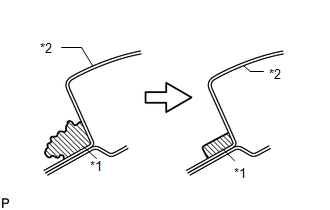
(c) Pass a piano wire between the vehicle body and back door glass from the interior, as shown in the illustration. HINT: Do not allow the piano wire to interfere with the clips. Text in Illustration
|
|

(d) Tie both wire ends to wooden blocks or similar objects that can serve as handles.
(e) Cut off the adhesive by pulling the piano wire around the back door glass.
NOTICE:
Leave as much adhesive on the vehicle body as possible when removing the back door glass.
|
(f) Place matchmarks on the back door glass and vehicle body on the locations indicated in the illustration. Text in Illustration
HINT: Matchmarks are not necessary if the back door glass is not going to be reused. |
|
.png)
|
(g) Using suction cups, disengage the 2 clips and remove the back door glass. |
|
.png)
13. REMOVE BACK DOOR GLASS SPACER
|
(a) Remove the 4 back door glass spacers. |
|

14. REMOVE NO. 2 BACK WINDOW GLASS SPACER
|
(a) Using a scraper, remove the No. 2 back window glass spacer. NOTICE:
|
|
15. REMOVE NO. 1 BACK WINDOW GLASS SPACER
HINT:
Use the same procedure for the RH side and LH side.
16. CLEAN BACK DOOR GLASS
|
(a) Clean the outer edge of the back door glass with a non-residue solvent. NOTICE:
|
|
17. CLEAN VEHICLE BODY
|
(a) Using a scraper, remove the moulding and adhesive from the back door glass. Text in Illustration
|
|
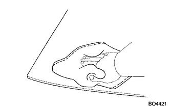
(b) Clean and shape the contact surfaces of the vehicle body.
(1) Using a knife, cut away excess adhesive on the contact surfaces of the vehicle body, as shown in the illustration.
NOTICE:
Be careful not to damage the vehicle body.
HINT:
Leave as much adhesive on the vehicle body as possible.
(2) Clean the contact surfaces of the vehicle body with a piece of cloth saturated with cleaner.
HINT:
Even if all the adhesive has been removed, clean the vehicle body.
 Installation
INSTALLATION
PROCEDURE
1. INSTALL NO. 2 BACK WINDOW GLASS SPACER
(a) Apply Primer G to the installation part of the No. 2 back window glass spacer.
HINT:
If primer is applied to an area that is n ...
 Front Passenger Side Power Window Switch
Components
COMPONENTS
ILLUSTRATION
Removal
REMOVAL
PROCEDURE
1. REMOVE POWER WINDOW REGULATOR SWITCH ASSEMBLY WITH FRONT DOOR ARMREST BASE
PANEL
(a) Using a moulding remover, ...
Other materials about Toyota Venza:
Microphone Circuit between Microphone and Navigation Receiver Assembly
DESCRIPTION
The navigation receiver assembly and inner rear view mirror assembly
(amplifier microphone assembly) are connected to each other using the microphone
connection detection signal lines.
Using this circuit, the navigation receiver ...
Removal
REMOVAL
PROCEDURE
1. REMOVE INSTRUMENT PANEL SAFETY PAD ASSEMBLY
(See page )
2. REMOVE NO. 1 ANTENNA CORD SUB-ASSEMBLY
(a) Disengage the 7 clamps and remove the No. 1 antenna cord sub-assembly.
3. REMOVE ROOF HEADLINING ASSEMBLY
(See page )
4. REMO ...
Terminals Of Ecu
TERMINALS OF ECU
NOTICE:
Turn the ignition switch off before measuring the resistances between
CAN bus main wires and between CAN bus branch wires.
Turn the ignition switch off before inspecting CAN bus wires for a ground
short.
After ...

0.147