Toyota Venza: Removal
REMOVAL
PROCEDURE
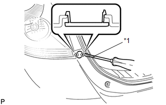
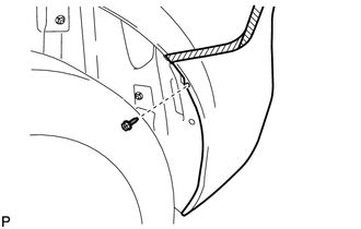
1. REMOVE REAR BUMPER PLATE LH
|
(a) Using a screwdriver with the tip wrapped with protective tape, disengage the 2 claws and remove the rear bumper plate LH. Text in Illustration
|
|
2. REMOVE REAR BUMPER PLATE RH
HINT:
Use the same procedure for the RH side and LH side.
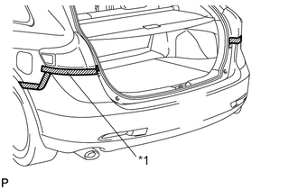
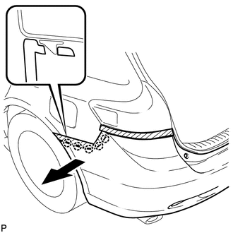
3. REMOVE REAR BUMPER ASSEMBLY
|
(a) Put protective tape around the rear bumper assembly. Text in Illustration
|
|
|
(b) Remove the 2 bolts and 2 screws. |
|
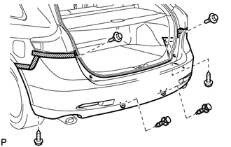
(c) Using a clip remover, remove the 2 clips.
|
(d) Remove the 2 screws and 2 clips. |
|
|
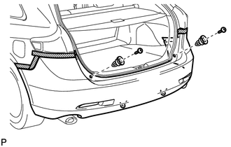
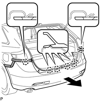
(e) Remove the screw. HINT: Use the same procedure for the RH side and LH side. |
|
|
(f) Disengage the 5 claws. HINT: Use the same procedure for the RH side and LH side. |
|
|
(g) Disengage the 6 claws as shown in the illustration. |
|
(h) w/ Intuitive Parking Assist System:
(1) Disconnect each connector.
(i) Remove the rear bumper assembly.
 Components
COMPONENTS
ILLUSTRATION
ILLUSTRATION
ILLUSTRATION
ILLUSTRATION
...
 Disassembly
DISASSEMBLY
PROCEDURE
1. REMOVE ULTRASONIC SENSOR CLIP (w/ Intuitive Parking Assist System)
2. REMOVE NO. 1 ULTRASONIC SENSOR (w/ Intuitive Parking Assist System)
3. REMOVE NO. 1 ULTRASONIC ...
Other materials about Toyota Venza:
Bank 1 Air-Fuel Ratio Imbalance (P219A,P219C-P219F)
DESCRIPTION
Refer to DTC P0300 (See page ).
Refer to DTC P2195 (See page ).
DTC No.
DTC Detection Condition
Trouble Area
P219A
The difference in air fuel ratios between the cylinders exceeds the ...
Vehicle Speed Sensor "A" (P0500)
DESCRIPTION
The speed sensor detects the wheel speed and sends the appropriate signals to
the skid control ECU.
The skid control ECU converts these wheel speed signals into a 4-pulse signal
and outputs it to the ECM via the combination meter. The ECM det ...
Disassembly
DISASSEMBLY
PROCEDURE
1. REMOVE TRANSMISSION WIRE
2. REMOVE ATF TEMPERATURE SENSOR ASSEMBLY
(a) Remove the 4 bolts, ATF temperature sensor assembly and clamp from
the valve body assembly.
Text in Illustration
*1
...

0.1477