Toyota Venza: Removal
REMOVAL
PROCEDURE
1. REMOVE BACK DOOR PANEL TRIM ASSEMBLY
.gif)
2. REMOVE REAR WIPER ARM HEAD CAP
3. REMOVE REAR WIPER ARM AND BLADE ASSEMBLY
4. REMOVE REAR WIPER MOTOR GROMMET
5. REMOVE REAR WIPER MOTOR AND BRACKET ASSEMBLY
6. REMOVE REAR LIGHT ASSEMBLY LH
7. REMOVE REAR LIGHT ASSEMBLY RH
HINT:
Use the same procedure for the RH side and LH side.
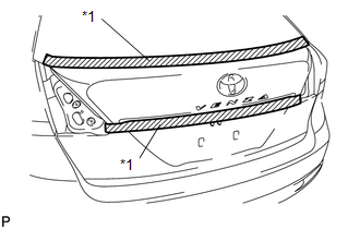
8. REMOVE BACK DOOR OUTSIDE GARNISH SUB-ASSEMBLY
|
(a) Put protective tape around the back door outside garnish sub-assembly. Text in Illustration
|
|
(b) Disconnect each connector.
|
(c) Remove the 5 nuts. |
|
.png)
|
(d) Disengage the 16 clips and remove the back door outside garnish sub-assembly. |
|
.png)
(e) Remove the 16 clips (back door moulding clip) from the back door outside garnish sub-assembly.
(f) Remove the 5 gaskets and 5 stud bolts from the back door outside garnish sub-assembly.
9. REMOVE NO. 1 BACK DOOR EMBLEM
10. REMOVE NO. 2 BACK DOOR NAME PLATE
11. REMOVE BACK DOOR OPENER SWITCH ASSEMBLY
12. REMOVE TELEVISION CAMERA ASSEMBLY (w/ Rear View Monitor System)
 Installation
INSTALLATION
PROCEDURE
1. INSTALL TELEVISION CAMERA ASSEMBLY (w/ Rear View Monitor System)
2. INSTALL BACK DOOR OPENER SWITCH ASSEMBLY
3. INSTALL NO. 1 BACK DOOR EMBLEM
4. INSTALL NO. 2 ...

Other materials about Toyota Venza:
Adjustment
ADJUSTMENT
PROCEDURE
1. INSPECT SHIFT LEVER POSITION
(a) When moving the lever from P to R with the ignition switch ON and the brake
pedal depressed, make sure that the shift lever moves smoothly and moves correctly
into position.
(b) Start the engine ...
Outer Mirror Control Ecu
Components
COMPONENTS
ILLUSTRATION
Removal
REMOVAL
PROCEDURE
1. REMOVE FRONT DOOR INSIDE HANDLE BEZEL PLUG
2. REMOVE POWER WINDOW REGULATOR MASTER SWITCH ASSEMBLY WITH FRONT DOOR ARMREST
BASE PANEL (for Driver Side)
3. REMOVE POWER WINDOW ...
Starting System
Parts Location
PARTS LOCATION
ILLUSTRATION
ILLUSTRATION
System Diagram
SYSTEM DIAGRAM
...

0.1164