Toyota Venza: Removal
REMOVAL
PROCEDURE
1. REMOVE REAR WHEELS
2. REMOVE CENTER EXHAUST PIPE ASSEMBLY
(a) Remove the center exhaust pipe assembly.
HINT:
Refer to the instructions for Removal of the exhaust pipe (See page
.gif) for 2GR-FE,
for 2GR-FE, .gif)
for 1AR-FE).
3. REMOVE PROPELLER WITH CENTER BEARING SHAFT ASSEMBLY
.gif)
4. SEPARATE REAR HEIGHT CONTROL SENSOR SUB-ASSEMBLY (w/ HID Headlight System)
|
(a) Remove the nut and separate the rear height control sensor sub-assembly from the rear No. 2 suspension arm assembly RH. NOTICE: Use wire or an equivalent tool to keep the rear height control sensor link from hanging down. |
|
5. SEPARATE NO. 3 PARKING BRAKE CABLE ASSEMBLY
.gif)
6. SEPARATE NO. 2 PARKING BRAKE CABLE ASSEMBLY
HINT:
Perform the same procedure as the LH side.
7. REMOVE REAR STRUT ROD ASSEMBLY LH
.gif)
8. REMOVE REAR STRUT ROD ASSEMBLY RH
HINT:
Perform the same procedure as the LH side.
9. REMOVE REAR NO. 2 SUSPENSION ARM ASSEMBLY LH
|
(a) Put matchmarks on the adjust cams and the rear suspension member sub-assembly. Text in Illustration
|
|
(b) Remove the bolt (A) and the nut, and separate the rear No. 2 suspension arm assembly LH from the rear axle carrier sub-assembly LH.
NOTICE:
Since a stopper nut is used, loosen the bolt.
(c) Remove the nut (B), the No. 2 camber adjust cam, the rear suspension toe adjust cam sub-assembly, and the rear No. 2 suspension arm assembly LH.
HINT:
When removing the nut, keep the rear suspension toe adjust cam sub-assembly from rotating.
10. REMOVE REAR NO. 2 SUSPENSION ARM ASSEMBLY RH
HINT:
Perform the same procedure as the LH side.
11. SEPARATE REAR NO. 1 SUSPENSION ARM ASSEMBLY LH
|
(a) Remove the bolt and the nut, and separate the rear No. 1 suspension arm assembly LH from the rear axle carrier sub-assembly LH. NOTICE: Since a stopper nut is used, loosen the bolt. |
|
12. SEPARATE REAR NO. 1 SUSPENSION ARM ASSEMBLY RH
HINT:
Perform the same procedure as the LH side.
13. REMOVE NO. 1 FLOOR UNDER COVER
|
(a) Separate the 5 clips to remove the No. 1 floor under cover. HINT: Remove the No. 1 floor under cover with the 5 clips. |
|
14. SEPARATE FRAME WIRE
|
(a) Disengage the 2 clamps to separate the frame wire from the body. |
|
15. SEPARATE NO. 3 FLOOR WIRE (w/ HID Headlight System)
|
(a) Disconnect the connector and disengage the clamp to separate the No. 3 floor wire from the rear suspension member. |
|
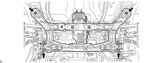
16. SEPARATE REAR SUSPENSION MEMBER
|
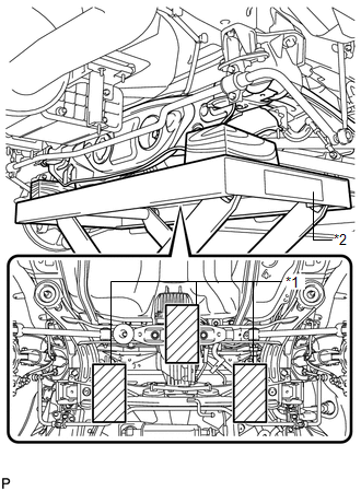
(a) Support the rear suspension member with a jack using 3 wooden blocks as shown in the illustration. Text in Illustration
HINT: Use properly sized wooden blocks to keep the jack and suspension member level. |
|
(b) Remove the 4 nuts, 2 bolts and 2 rear lower suspension member stopper retainers.

|
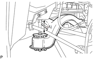
(c) Lower the rear suspension member to the point shown in the illustration. Length (A): 100 mm (3.94 in.) |
|
17. REMOVE REAR NO. 1 SUSPENSION ARM ASSEMBLY LH
|
(a) Remove the bolt, the nut and the rear No. 1 suspension arm assembly LH from the rear suspension member. NOTICE: Since a stopper nut is used, loosen the bolt. |
|
18. REMOVE REAR NO. 1 SUSPENSION ARM ASSEMBLY RH
HINT:
Perform the same procedure as the LH side.
 Installation
INSTALLATION
PROCEDURE
1. INSTALL REAR NO. 1 SUSPENSION ARM ASSEMBLY LH
(a) Temporarily install the rear No. 1 suspension arm assembly LH to
the rear suspension member with the bolt ...
Other materials about Toyota Venza:
Calibration
CALIBRATION
1. ROTATION ANGLE SENSOR INITIALIZATION AND TORQUE SENSOR ZERO POINT CALIBRATION
NOTICE:
Clear the rotation angle sensor calibration value, initialize the rotation angle
sensor, and calibrate the torque sensor zero point if any of the followin ...
Room Light
Components
COMPONENTS
ILLUSTRATION
Removal
REMOVAL
PROCEDURE
1. REMOVE SPOT LIGHT ASSEMBLY
(a) Using a screwdriver with its tip wrapped with protective tape, disengage
the 8 claws to remove the 2 spot light lenses.
Text in Illust ...
GPS Mark is not Displayed
PROCEDURE
1.
CHECK CABIN
(a) Check the cabin for any object that might interrupt radio reception or additional
devices which use radio waves on the instrument panel. If such an object exists,
remove it and check if the GPS ...
0.1556

.png)
.png)
.png)
.png)
.png)
.png)


.png)
