Toyota Venza: Removal
REMOVAL
PROCEDURE
1. REMOVE FRONT WHEELS
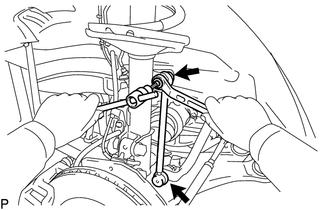
2. REMOVE FRONT STABILIZER LINK ASSEMBLY LH
|
(a) Remove the 2 nuts and front stabilizer link assembly LH. HINT: If the ball joint turns together with the nut, use a hexagon wrench (6 mm) to hold the stud bolt. |
|
3. REMOVE FRONT STABILIZER LINK ASSEMBLY RH
HINT:
Perform the same procedure as for the LH side.
4. REMOVE FRONT FRAME ASSEMBLY
for 1AR-FE: (See page .gif) )
)
for 2GR-FE: (See page )
5. REMOVE STEERING LINK ASSEMBLY
6. REMOVE FRONT STABILIZER BAR
(a) Remove the front stabilizer bar from the vehicle.
7. REMOVE FRONT NO. 1 STABILIZER BRACKET LH
(a) Remove the front No. 1 stabilizer bracket LH from the front No. 1 stabilizer bar bushing.
8. REMOVE FRONT NO. 1 STABILIZER BRACKET RH
HINT:
Perform the same procedure as for the LH side.
9. REMOVE FRONT NO. 2 STABILIZER BRACKET LH
|
(a) Remove the front No. 2 stabilizer bracket LH from the front No. 1 stabilizer bar bushing. |
|
.png)
10. REMOVE FRONT NO. 2 STABILIZER BRACKET RH
HINT:
Perform the same procedure as for the LH side.
11. REMOVE FRONT NO. 1 STABILIZER BAR BUSHING
(a) Remove the 2 front No. 1 stabilizer bar bushings from the front stabilizer bar.
 Components
COMPONENTS
ILLUSTRATION
...
 Inspection
INSPECTION
PROCEDURE
1. INSPECT FRONT STABILIZER LINK ASSEMBLY
(a) Inspect the turning torque of the ball joint.
(1) Secure the front stabilizer link assembly in a vise using aluminum ...
Other materials about Toyota Venza:
Precaution
PRECAUTION
NOTICE:
When disconnecting the cable from the negative (-) battery terminal, initialize
the following systems after the cable is reconnected.
System Name
See Procedure
Back Door Closer System
...
Installation
INSTALLATION
CAUTION / NOTICE / HINT
HINT:
Use the same procedure for the RH side and LH side.
The following procedure is for the LH side.
The rear speed sensor is a component of the rear axle hub and bearing
assembly. If the sensor malf ...
Test Mode Procedure
TEST MODE PROCEDURE
1. DESCRIPTION
HINT:
When using a chassis dynamometer, brake tester, etc. to perform a vehicle test,
activate test mode to avoid a "different tire diameter installed" incorrect judgment.
Test mode does not have a AWD paramet ...

0.1145